Metal-organic vaporizing and feeding apparatus, metal-organic chemical vapor deposition apparatus, metal-organic chemical vapor deposition method, gas flow rate regulator, semiconductor manufacturing apparatus, and semiconductor manufacturing method

a technology of feeding apparatus, which is applied in chemical vapor deposition coating, metal-organic chemical vapor deposition methods, semiconductor manufacturing apparatuses, etc., can solve the problems of complex apparatus, increase the cost of deposition by mocvd method, and complicate the conventional metal-organic vaporizing and feeding apparatus. , to achieve the effect of simplifying the apparatus

Inactive Publication Date: 2007-12-20
SUMITOMO ELECTRIC IND LTD +1
View PDF1 Cites 14 Cited by
  • Summary
  • Abstract
  • Description
  • Claims
  • Application Information

AI Technical Summary

Benefits of technology

[0013]It is an object of the present invention to provide a metal-organic vaporizing and feeding apparatus, a metal-organic chemical vapor deposition apparatus, a metal-organic chemical vapor deposition method, a gas flow rate regulator, a semiconductor manufacturing apparatus, and a semiconductor manufacturing method capable of simplifying the apparatus.

Problems solved by technology

Therefore, the conventional metal-organic vaporizing and feeding apparatus involves the problem of complexity of apparatus.
Further, since the apparatus is complex, production costs for the metal-organic vaporizing and feeding apparatus increase, and costs for deposition by the MOCVD method increase.

Method used


Image

  • Metal-organic vaporizing and feeding apparatus, metal-organic chemical vapor deposition apparatus, metal-organic chemical vapor deposition method, gas flow rate regulator, semiconductor manufacturing apparatus, and semiconductor manufacturing method
  • Metal-organic vaporizing and feeding apparatus, metal-organic chemical vapor deposition apparatus, metal-organic chemical vapor deposition method, gas flow rate regulator, semiconductor manufacturing apparatus, and semiconductor manufacturing method
  • Metal-organic vaporizing and feeding apparatus, metal-organic chemical vapor deposition apparatus, metal-organic chemical vapor deposition method, gas flow rate regulator, semiconductor manufacturing apparatus, and semiconductor manufacturing method

Examples


first embodiment

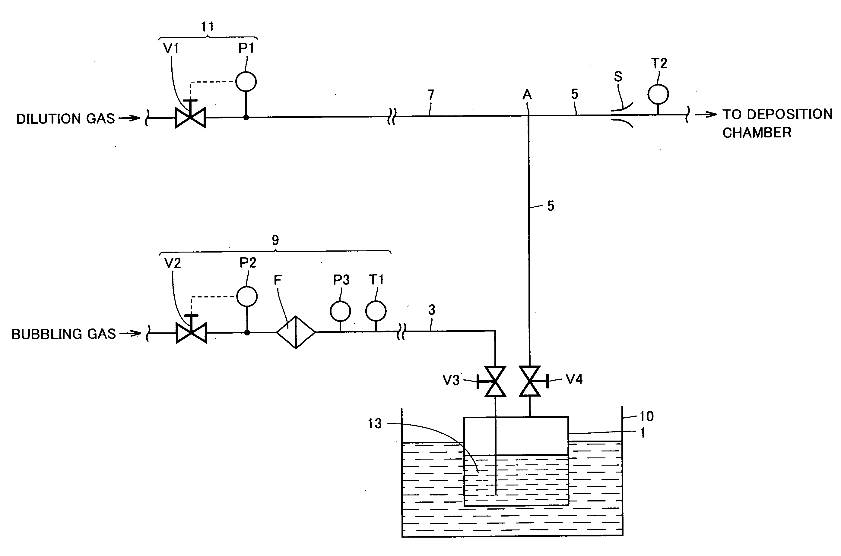
[0058]Referring to FIG. 1, a metal-organic vaporizing and feeding apparatus according to the present Embodiment includes a retention vessel 1, a bubbling gas feeding path 3, a metal-organic gas feeding path 5, a dilution gas feeding path 7, a flow rate regulator 9 serving as a gas flow rate regulator, a thermostat bath 10, a pressure regulator 11, a sonic nozzle S serving as a restrictor, valves V3 and V4, and a thermometer T2.

[0059]Within retention vessel 1, liquid of a metal-organic material 13 is retained, and on the upstream side of retention vessel 1, bubbling gas feeding path 3 is connected. Bubbling gas feeding path 3 extends to reach inside metal-organic material 13. Bubbling gas feeding path 3 is provided with flow rate regulator 9 for regulating flow rate of bubbling gas. On the downstream side of retention vessel 1, metal-organic gas feeding path 5 is connected. Metal-organic gas feeding path 5 is connected at a position where it does not come into contact with liquid met...

second embodiment

[0086]Referring to FIG. 5, a MOCVD apparatus in the present Embodiment includes a metal-organic vaporizing and feeding apparatus 20, a gas feeding path 19, and a deposition chamber 17. Metal-organic vaporizing and feeding apparatus 20 and gas feeding path 19 are both connected to deposition chamber 17, and feed deposition chamber 17 with different gases.

[0087]Metal-organic vaporizing and feeding apparatus 20 in the present Embodiment is different from the metal-organic vaporizing and feeding apparatus of First Embodiment in that H2 or N2 may be used as bubbling gas and dilution gas, and sonic nozzle may be switched depending on the kind of bubbling gas and dilution gas. In the following, the makeup of metal-organic vaporizing and feeding apparatus 20 will be explained.

[0088]In metal-organic vaporizing and feeding apparatus 20, there is provided a connecting path 15 that connects bubbling gas feeding path 3 on the upstream side of valve V2 and dilution gas feeding path 7 on the upstr...

third embodiment

[0103]Referring to FIG. 6, a metal-organic vaporizing and feeding apparatus 20 in the present Embodiment differs from metal-organic vaporizing and feeding apparatus of Second Embodiment shown in FIG. 5 in that a dilution gas flow rate measuring part 16 is provided. In the following, the makeup of metal-organic vaporizing and feeding apparatus 20 will be explained.

[0104]Between valve V1 and manometer P1 in dilution gas feeding path 7, there is provided dilution gas flow rate measuring part 16. Dilution gas flow rate measuring part 16, a manometer P4 serving as manometer for dilution gas, a laminar flow element F2 serving as element for dilution gas, and a thermometer T3 in this order from upstream side. Bubbling gas feeding path 3 has a first bubbling gas feeding path 3a and a second bubbling gas feeding path 3b. On the down stream side of the connection position with connecting path 15, first bubbling gas feeding path 3a and second bubbling gas feeding path 3b are branched, and at t...


PUM

PropertyMeasurementUnit
flow rateaaaaaaaaaa
pressureaaaaaaaaaa
dilution gas flow rateaaaaaaaaaa

Abstract

A metal-organic vaporizing and feeding apparatus includes: a retention vessel for retaining a metal-organic material; a bubbling gas feeding path connected to the retention vessel, for feeding bubbling gas to the metal-organic material; a metal-organic gas feeding path connected to the retention vessel, for feeding metal-organic gas generated in the retention vessel and dilution gas to a deposition chamber; a dilution gas feeding path connected to the metal-organic gas feeding path, for feeding the dilution gas to the metal-organic gas feeding path; a flow rate regulator provided in the bubbling gas feeding path, for regulating flow rate of the bubbling gas; a pressure regulator for regulating pressure of the dilution gas; and a sonic nozzle disposed in the metal-organic gas feeding path on a downstream side of a connecting position between the metal-organic gas feeding path and the dilution gas feeding path.

Description

BACKGROUND OF THE INVENTION[0001]1. Field of the Invention[0002]The present invention relates to metal-organic vaporizing and feeding apparatuses, metal-organic chemical vapor deposition apparatuses, metal-organic chemical vapor deposition methods, gas flow rate regulators, semiconductor manufacturing apparatuses, and semiconductor manufacturing methods, and more specifically, to a metal-organic vaporizing and feeding apparatus, a metal-organic chemical vapor deposition apparatus, a metal-organic chemical vapor deposition method, a gas flow rate regulator, a semiconductor manufacturing apparatus, and a semiconductor manufacturing method which are used for deposition of a nitride compound semiconductor.[0003]2. Description of the Background Art[0004]The Metal-Organic Chemical Vapor Deposition (MOCVD) method is one of representative vapor phase deposition methods, in which vaporized metal-organic is thermally decomposed on a surface of a substrate and a deposition film is formed there...

Claims


Application Information

Patent Timeline
Patent Type & Authority Applications(United States)
IPC IPC(8): C23C16/00
CPCC23C16/52C23C16/4482
Inventor UENO, MASAKIUEDA, TOSHIONAKAMURA, TAKAOISHIKAWA, KOICHITAKAHASHI, KENYASAKU, OSAMUUJIIE, KAZUOTAKEMOTO, KIKUROU
Owner SUMITOMO ELECTRIC IND LTD
Why Eureka
Try Eureka