Sealed battery with a film casing

a film casing and battery technology, applied in the field of sealed batteries with film casings, can solve the problems of difficult bending of the part covered by the insulating resin layer, electrode terminal cuts, reliability problems, etc., and achieve the effect of convenient bending, reduced battery module size, and improved safety

Active Publication Date: 2007-12-20
NEC ENERGY DEVICES LTD
View PDF6 Cites 32 Cited by
  • Summary
  • Abstract
  • Description
  • Claims
  • Application Information

AI Technical Summary

Benefits of technology

[0019]In addition, according to the present invention, when the positive and the negative electrode terminals of the battery with the film casing are connected to a protective element, or when the electrode terminals are connected with each other in series or in parallel, the electrode terminals can be easily bent. Further, downsizing of a battery module can be achieved while reliability of a pulled-out terminal part after the bending is ensured. In addition, a function of a current fuse can be added by adjusting the size of the notched part provided on the electrode terminal, therefore a battery with higher safety can be provided.

Problems solved by technology

Therefore, it has been difficult to bend the part covered by the insulating resin layer.
However, when the electrode terminals 4A and 4B are bent at an edge of the insulating resin layer 6, there has been a possibility that the electrode terminals are cut due to lower strength against bending.
Therefore, there has been a problem in terms of reliability.

Method used


Image

  • Sealed battery with a film casing
  • Sealed battery with a film casing
  • Sealed battery with a film casing

Examples


example 1

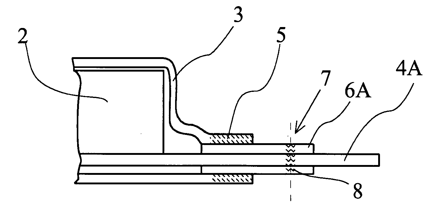
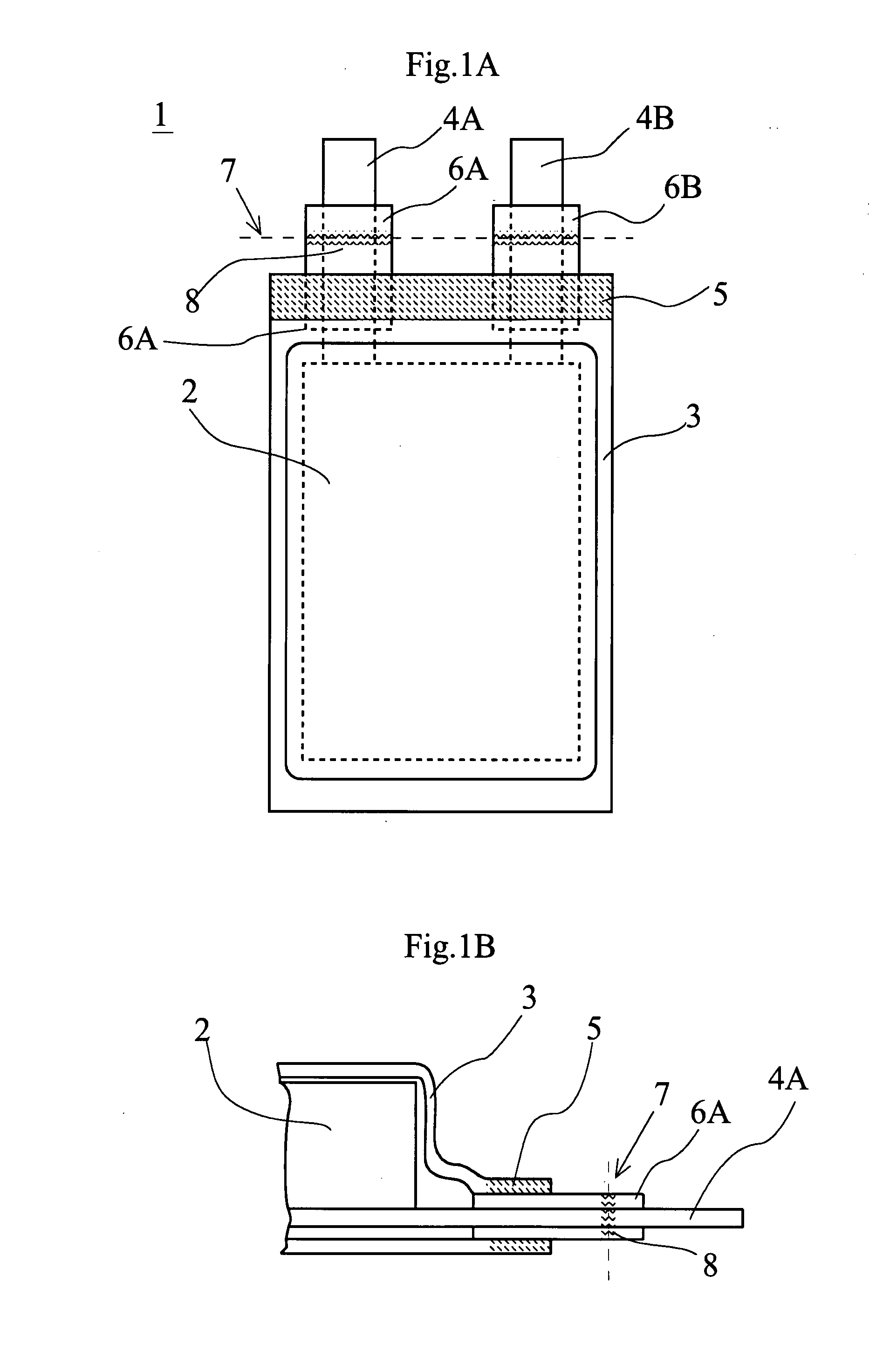
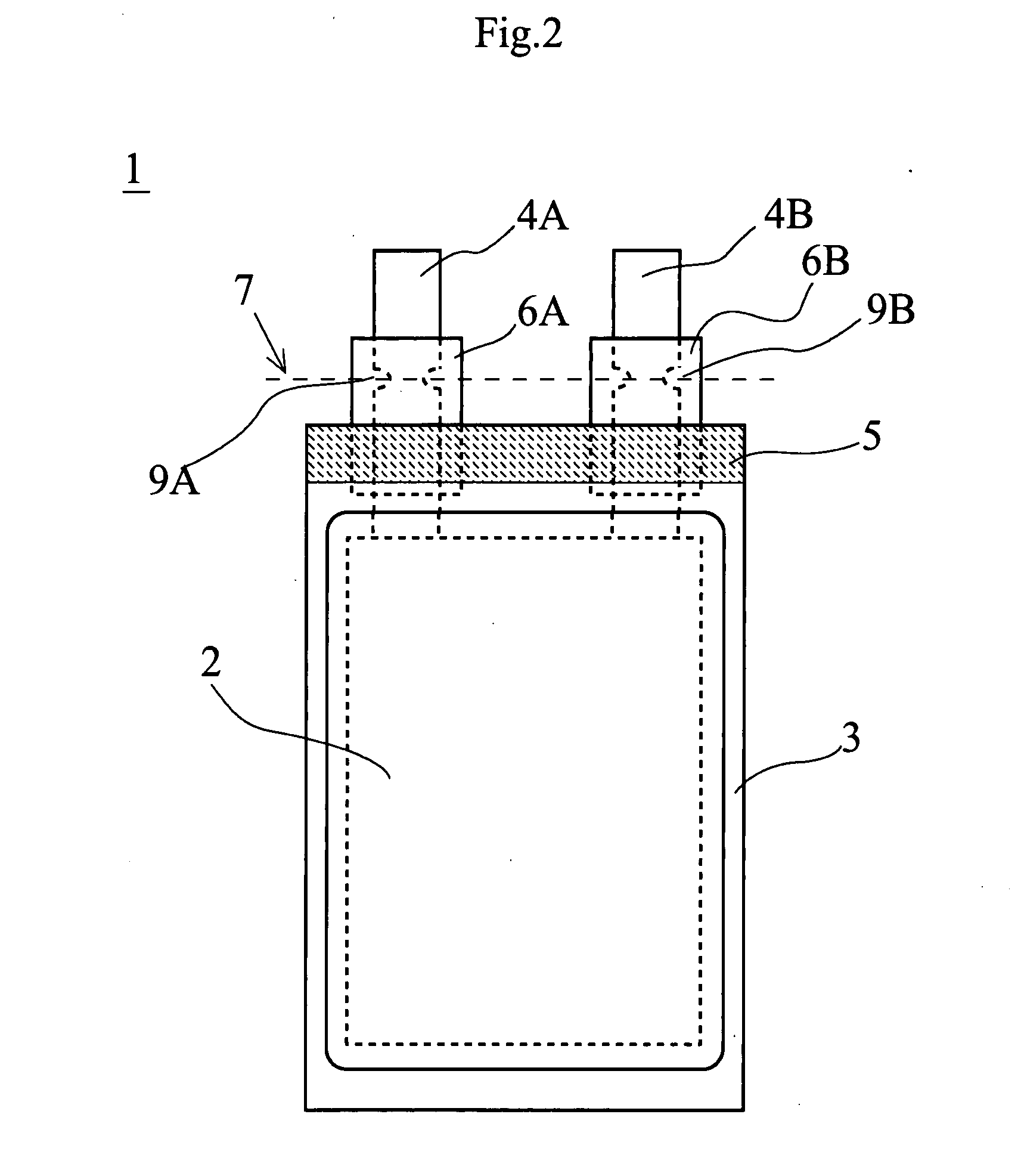
[0071]The electrode terminal shown in FIG. 2 was manufactured. The positive electrode terminal 4A had width of 10 mm and thickness of 0.2 mm, and was made of aluminum, and the negative electrode terminal 4B has width of 10 mm and thickness of 0.2 mm, and was made of copper. After the notch part 9 having a semi-ellipse shape with length of 5 mm and breadth of 3 mm was formed on each of the electrode terminals, and each of the electrode terminals was covered by the insulating resin 6 of thickness of 0.1 mm.

[0072]In addition, the sealing part 5 formed by the heat welding was provided with width of 9 mm. The insulating resin layer 6 extended from the sealing part with length of 13 mm and width of 17 mm. The notch part 9 was located inside a front edge of the insulating layer for 6 mm.

[0073]Due to a structure of the terminal portion, bending along the bending line 7 was facilitated. In addition, the electrode terminals 4A and 4B were bent at a part covered by the insulating resin layer 6...

example 2

[0074]The pulled out portion in the present example is in a shape shown in FIG. 3, where the pulled out portion was manufactured in a similar manner as the example 1 except that the void parts 10A and 10B each of which was one circular through hole was provided in place of two of the notch parts 9A and 9B in a semi-ellipse shape shown in FIG. 2. The diameter of the void parts 10A and 10B was 5 mm, and the center of each of the void parts was allocated at a position 6 mm inside the front edge of the insulating resin layer 6.

[0075]In addition, the battery shown in FIG. 3 was manufactured by forming the insulating resin layer after punching a predetermined part of the electrode terminal in advance to form the circular void part. However, the present embodiment may be such that processing of punching in a circular shape is carried out for the electrode terminal covered by the insulating resin layers 6A and 6B after the battery is manufactured to provide the void part on both of the insu...

example 3

[0077]The pulled out part in the present example is in a shape shown in FIG. 4, where the notch parts 11A and 11B of a semi-ellipse shape were formed on both sides of the insulating resin layers 6A and 6B in a width direction. The insulating resin layer extending outward from the sealing part had width of 17 mm, height of 24 mm and thickness of 0.1 mm.

[0078]In addition, the semi-ellipse of the notch parts 11A and 11B had length of 5 mm and breadth of 3 mm, and was formed on the battery completed by carrying out sealing processing of the battery before the bending processing of the electrode terminal. A terminal structure in which the bending of the electrode terminal is easy and having high reliability of mechanical strength after the bending is obtained.

[0079]In addition, according to the example 3, the present invention has a characteristic that adjustment of a position of the notch part at the time of mounting the battery is made possible.


PUM

PropertyMeasurementUnit
thicknessaaaaaaaaaa
widthaaaaaaaaaa
widthaaaaaaaaaa

Abstract

A sealed battery with a film casing, comprising: a film casing covering a battery element; an electrode terminal pulled out by being conductive-connected to a positive electrode and a negative electrode of the battery element is taken out from a sealing part of the film casing; and a part of the electrode terminal between a portion positioned at the sealing part of the electrode terminal and a part of a portion of the electrode terminal extending outward beyond the sealing part being covered by an insulating resin layer, a region with low strength against bending being formed at the insulating resin layer positioned at a part extending outward beyond the sealing part or a part of the electrode terminal positioned at a lower layer of the insulating resin layer positioned at a part extending outward beyond the sealing part.

Description

CROSS-REFERENCE TO RELATED APPLICATIONS[0001]This application is based upon and claims the benefit of priority from prior Japanese Patent Application No. 2006-167372, filed Jun. 16, 2006, the entire contents of which are incorporated herein by reference.BACKGROUND OF THE INVENTION[0002]1. Field of the Invention[0003]The present invention relates to a battery with a film casing and a method of manufacturing the same, and more particularly, to a sealed battery with a film casing having a reliable terminal structure.[0004]2. Description of the Related Art[0005]In recent years, to meet a demand of a battery having higher capacity and smaller size, a lithium ion battery has been used as a power source of mobile equipment such as a mobile phone and a digital still camera. In addition, the lithium ion battery which has a high energy density and does not have a memory effect is also used as a power source for an electric bicycle, an electric tool, or an electric car. Smaller size is require...

Claims


Application Information

Patent Timeline
Patent Type & Authority Applications(United States)
IPC IPC(8): H01M2/06H01M2/08H01M50/528H01M50/178H01M50/548H01M50/55H01M50/557
CPCH01M2/0212H01M10/0525H01M2/30H01M2/26Y02E60/10H01M50/557H01M50/55H01M50/178H01M50/548
Inventor ZAMA, KOICHITOCHIHARA, ISAO
Owner NEC ENERGY DEVICES LTD
Why Eureka
Try Eureka