Fatigue resistant endoprostheses

Inactive Publication Date: 2007-12-20
ABBOTT LAB INC
View PDF7 Cites 30 Cited by
  • Summary
  • Abstract
  • Description
  • Claims
  • Application Information

AI Technical Summary

Benefits of technology

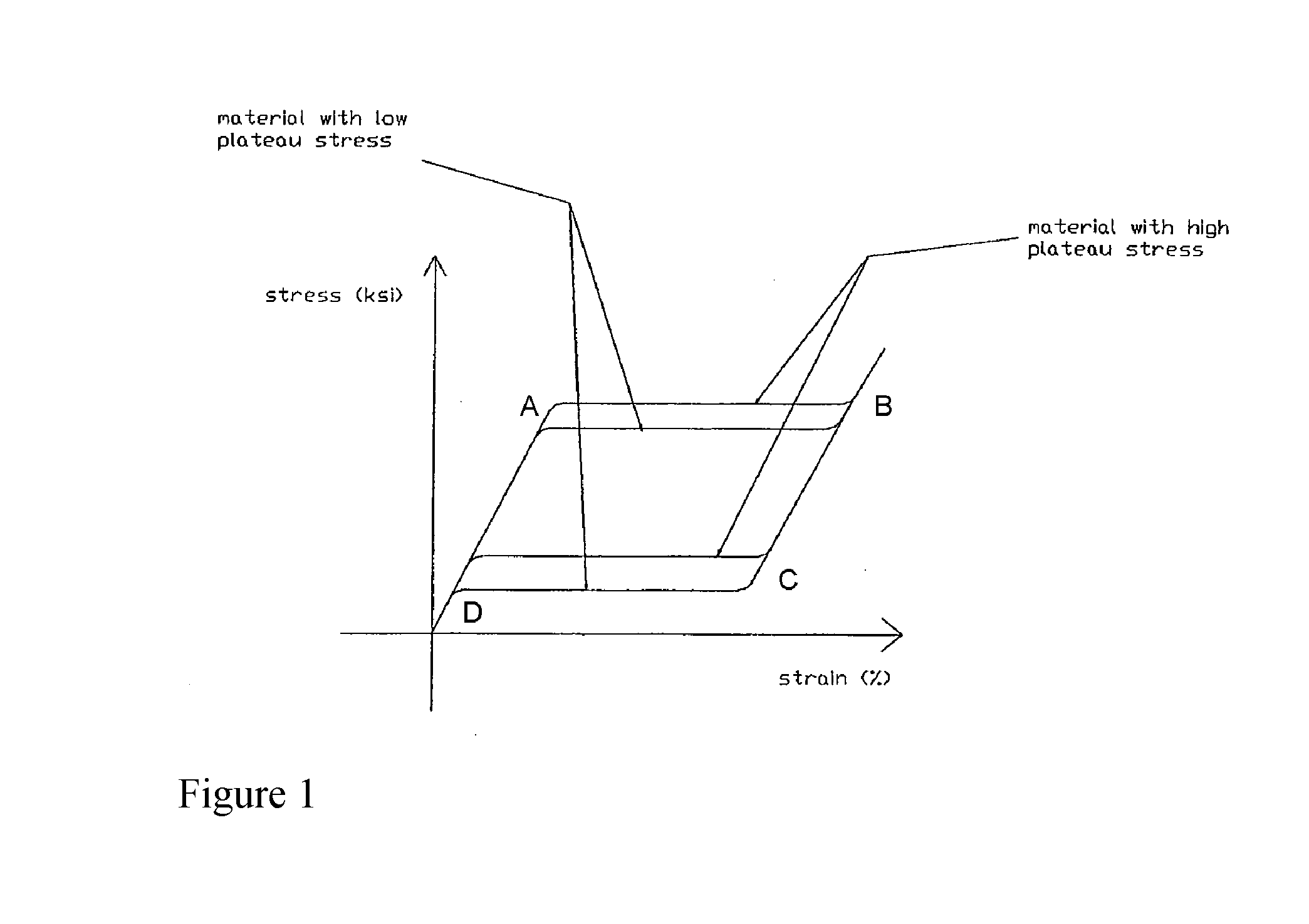
[0011] The present invention generally relates to superelastic endoprostheses having increased fatigue resistance and increased resistance to the formation of cracks. In particular, the present invention relates to methods for selectively increasing the austenitic finish temperature of superelastic endoprostheses as well as to methods for selectively increasing the austenitic finish temperature of particular portions of superelastic endoprostheses. The methods of the present invention include heating cycles designed to impart particular stress plateaus and austenitic finish temperatures upon a superelastic endoprosthesis. The entire endoprosthesis may be he

Problems solved by technology

Due to the constant stresses and strains placed upon an endoprosthesis, microcracks may eventually form on the surface or within a superelastic endoprosthesis leading to structural failure of the endoprosthesis.
Increasing the overall strength of a superelastic endoprosthesis can lead to an endoprosthesis that

Method used


Image

  • Fatigue resistant endoprostheses
  • Fatigue resistant endoprostheses
  • Fatigue resistant endoprostheses

Examples


example 1

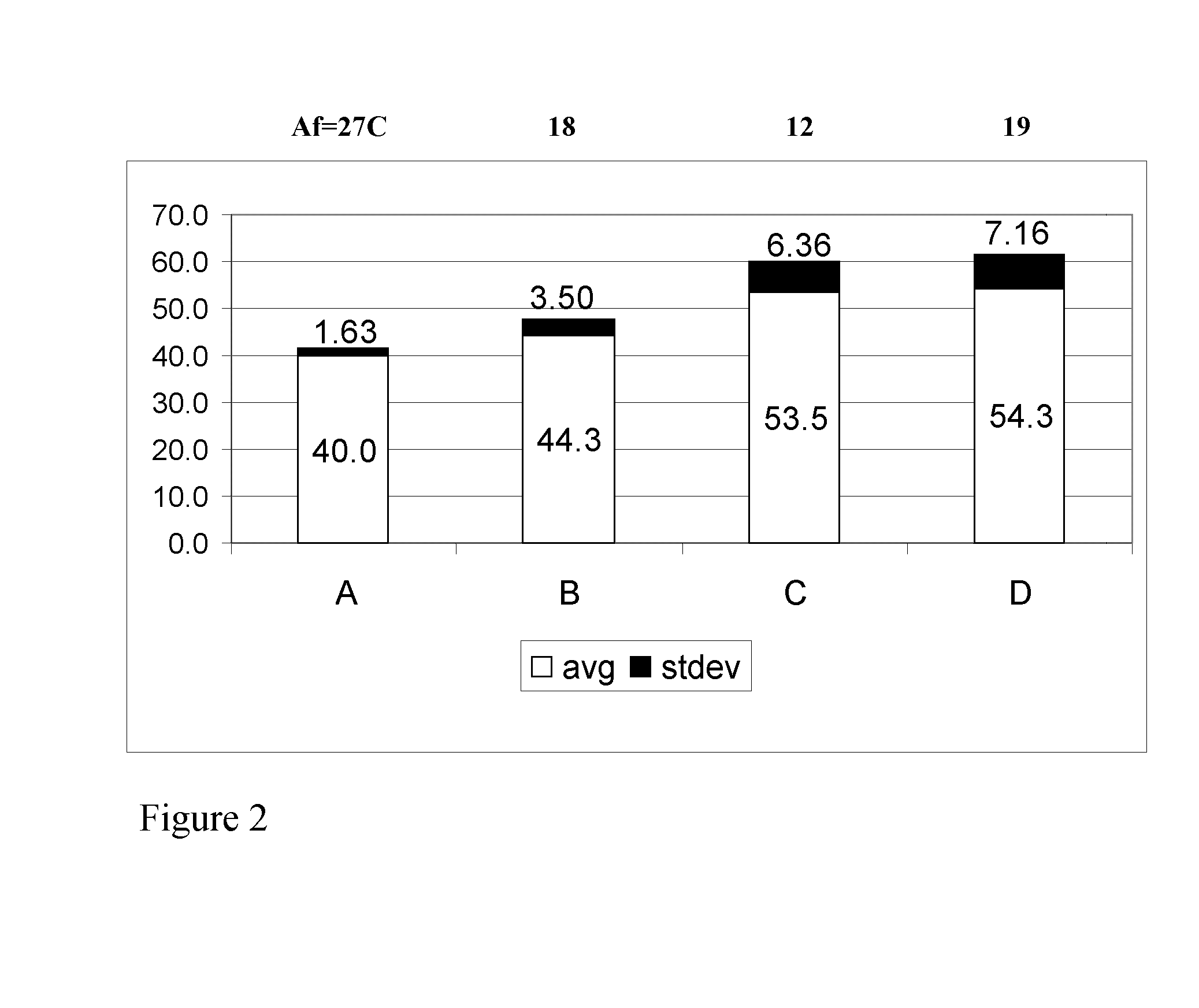
[0065] The autstenitic finish temperature was modulated in accordance with the present invention by heating an endoprosthesis as described in Methods A-D. In Method A, a superelastic tube was heated in a plurality of heating cycles to modulate the austenitic finish temperature by the following: a superelastic tubing having an inner diameter of 2 mm is heat treated at 500 degrees Celsius for 2 minutes and slidably disposed upon a mandrel having a diameter of 3 mm, then the superelastic tubing is quenched in water; the tubing is then heat treated at 500 degrees Celsius for 2 minutes and slidably disposed upon a mandrel having a diameter of 4 mm, then the superelastic tubing is quenched in water; the tubing is then heat treated at 500 degrees Celsius for 2 minutes and slidably disposed upon a mandrel having a diameter of 5 mm, then the superelastic tubing is quenched in water; and the tubing is then heat treated at 500 degrees Celsius for 4 minutes and slidably disposed upon a mandrel ...

example 2

[0070] In one embodiment, superelastic tubing is heat set and then subjected to an additional heat treatment for a duration ranging from 1 minute to 15 minutes and temperatures ranging from 350 degrees Celsius to 550 degrees Celsius. The resulting changes in austenitic finish temperatures of the superelastic tubing are compiled and depicted in Table 2.

TABLE 2Time ofChange in AfChange in AfChange in AfChange in AfChange in Afadditional(in Celsius)(in Celsius)(in Celsius)(in Celsius)(in Celsius)heatafterafterafterafteraftertreatmentadditionaladditionaladditionaladditionaladditionalafter heatheat treatmentheat treatmentheat treatmentheat treatmentheat treatmentsetat 350 Celsiusat 400 Celsiusat 450 Celsiusat 500 Celsiusat 550 Celsius 1 min.−2−1, 1, 6−12, 7 5 min.−22, 6.8, 7.7,1, 4.57.3, 7.1, 3.610 min.−3, −3.4, −3.1,9, 4.9, 16,3, 12.9−2.4, 2, 2.5, −3.115.8, 14.83.1, −2.8, −2.3,−215 min. 66.75, 15.7, 12.28, −0.6


PUM

PropertyMeasurementUnit
Temperatureaaaaaaaaaa

Abstract

A superelastic endoprosthesis can have improved fatigue resistance, and improved resistance to crack formation by being configuring to have an austenitic finish temperature from about 5 degrees Celsius to about 35 degrees Celsius, a stress-strain curve having an upper plateau stress from about 40 ksi to about 80 ksi, and a lower plateau stress from about 5 ksi to about 50 ksi. Such an endoprosthesis may be fabricated by heating at least a portion of the endoprosthetic body in a fluid, such as air, salt bath, or fluidized sand, having a temperature from about 400 degrees Celsius to about 600 degrees Celsius for at least about 30 seconds. Additionally, only portions of an endoprosthesis may selectively be subjected to the heating parameters of the present invention such that the endoprosthesis exhibits an increased radial stiffness and an increased flexibility in the longitudinal direction.

Description

CROSS-REFERENCE TO RELATED APPLICATIONS [0001] This U.S. patent application claims benefit of having U.S. provisional patent application Ser. No. 60 / 800,332, filed on May 15, 2006, entitled “FATIGUE AND FRACTURE RESISTANT STENTS THROUGH ALTERATION OF MECHANICAL PROPERTIES OF NITINOL,” and having Sanjay Shrivastava, and Kevin Kang as inventors, which U.S. provisional patent application is incorporated herein in its entirety by specific reference.BACKGROUND [0002] I. Technology Field [0003] The present invention relates to fatigue resistant superelastic endoprostheses. More particularly, the present invention relates to endoprostheses that have modulated austenitic finish temperatures and modulated plateau stresses. The present invention also relates to fatigue resistant superelastic endoprostheses having anisotropic stress measurements in the radial and longitudinal directions. [0004] II. The Related Technology [0005] Superelastic endoprostheses are subjected to multiple stresses and...

Claims


Application Information

Patent Timeline
IPC IPC(8): A61F2/06A61F2/82
CPCA61F2/82A61F2210/0019A61L31/022C22F1/10A61L2400/16C21D2201/01C22F1/006A61L31/14
Inventor SHRIVASTAVA, SANJAYKANG, KEVIN
Owner ABBOTT LAB INC
Why Eureka
Try Eureka