Air Bypass System for Gas turbine Inlet

a gas turbine and air bypass technology, applied in the direction of machines/engines, combustion-air/fuel-air treatment, separation processes, etc., can solve the problems of reducing the efficiency and power output of the turbine, reducing the efficiency and output of the gas turbine, etc., and achieve the effect of improving the efficiency of the gas turbine engin

Inactive Publication Date: 2007-12-27
GENERAL ELECTRIC CO
View PDF12 Cites 42 Cited by
  • Summary
  • Abstract
  • Description
  • Claims
  • Application Information

AI Technical Summary

Benefits of technology

[0011]The present application further describes a method of improving the efficiency of a gas turbine engine having an inlet filter house with a power augmentation system therein. The method may include increasing the airflow area about the power augmentation system when augmentation is not needed, engaging the power augmentation system to produce additional power, and confining the airflow to pass through the power augmentation system when the power augmentation system is operational.

Problems solved by technology

The higher the inlet system pressure drop, the lower the efficiency and power output of the turbine.
When the power augmentation system is not operating, however, the additional pressure drop that the system adds in the air inlet stream reduces the gas turbine efficiency and output.

Method used


Image

  • Air Bypass System for Gas turbine Inlet
  • Air Bypass System for Gas turbine Inlet
  • Air Bypass System for Gas turbine Inlet

Examples


Embodiment Construction

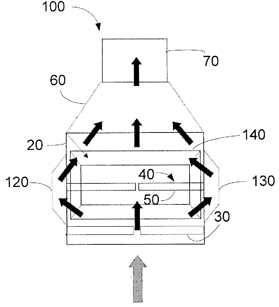
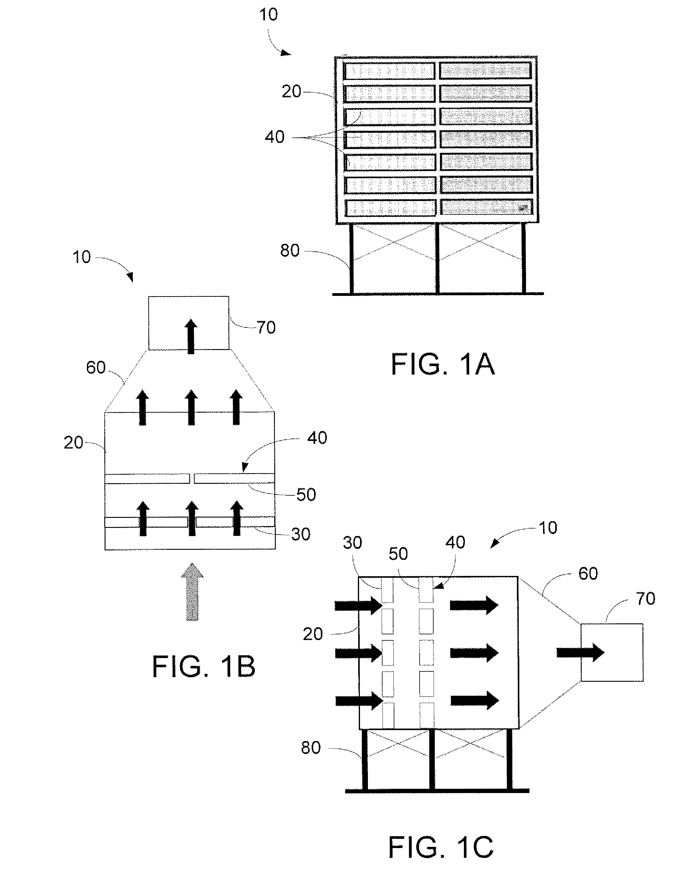
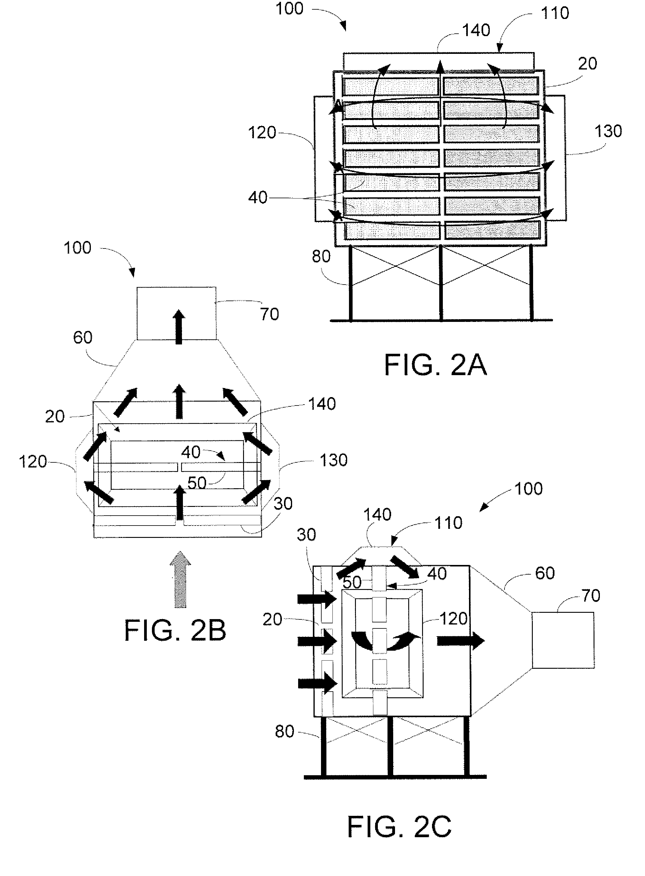
[0026]Referring now to the drawings, in which like numerals refer to like elements throughout the several views, FIGS. 1A-1C show a known inlet filter house 10. The inlet filter house 10 may be used with a gas turbine engine as is described above. The inlet filter house 10 includes a filter house envelope 20. The filter house envelope 20 is typically a box like structure with a number of filters 30 positioned therein. The filters 30 may be conventional filter devices so as to limit the intake of dust and debris into the gas turbine engine as a whole. Positioned within the filter house envelope 20 may be a power augmentation system 40. The power augmentation system 40 may include a chiller coil 50 or other types of chilling devices such as those described above. Positioned adjacent to the filter house envelope 20 may be a transition section 60. The transition section 60 narrows the airflow path so as to increase the airflow velocity. The transition section 60 may lead to an inlet duc...


PUM

PropertyMeasurementUnit
areaaaaaaaaaaa
pressure dropaaaaaaaaaa
temperatureaaaaaaaaaa

Abstract

An air bypass system for a gas turbine inlet filter house having a power augmentation system. The air bypass system may include a duct positioned on the inlet filter house about the power augmentation system and a damper positioned within the duct so as to open and close the duct.

Description

TECHNICAL FIELD[0001]The present application relates generally to gas turbines and more particularly relates to an air bypass system for a reduced pressure drop in a gas turbine in let.BACKGROUND OF THE INVENTION[0002]Generally described, gas turbine engines include a compressor for compressing incoming air, a combustor for mixing fuel with the compressed air and to ignite the fuel and the air to form a high temperature gas stream, and a turbine that is driven by the high temperature gas stream. Other components also may be used herein. The power of the gas turbine engine is related generally to the temperature of the gas flow at various locations therethrough. Specifically, the temperature at the compressor inlet, the compression ratio, and the temperature of the combustor outlet are closely monitored during operation of the engine. Lowering the temperature of the gas flow entering the compressor generally results in increasing the output of the engine.[0003]Known methods of reduci...

Claims


Application Information

Patent Timeline
Patent Type & Authority Applications(United States)
IPC IPC(8): B01D46/00
CPCF02C7/057F02C7/04F02C3/04F02C7/05
Inventor CHILLAR, RAHUL J.SMITH, RAUB WARFIELDSCIPIO, ALSTON ILFORD
Owner GENERAL ELECTRIC CO
Why Eureka
Try Eureka