Laminated Heat Exchanger

Inactive Publication Date: 2007-12-27
SHOWA DENKO KK
View PDF10 Cites 6 Cited by
  • Summary
  • Abstract
  • Description
  • Claims
  • Application Information

AI Technical Summary

Benefits of technology

[0027] According to the laminated heat exchanger of par. 1), the resistive portion is provided in at least one of the refrigerant-flow-dividing header sections so as to impart resistance to refrigerant that flows through the refrigerant channel extending in the longitudinal direction of the refrigerant-flow-dividing header section, so that there can be reduced the quantity of refrigerant that flows beyond the resistive portion in the refrigerant-flow-dividing header section. Accordingly, in the case where the laminated heat exchanger is used as an evaporator of a vehicle air conditioner, even when air-velocity distribution becomes nonuniform on the upstream side with respect to the air flow direction, and consequently air velocity drops in a region corresponding to the downstream side of the resistive portion with respect to the refrigerant flow direction in the refrigerant-flow-dividing header section, an extreme drop in the temperature of air that has passed through the region can be prevented. Thus, the temperature distribution of discharged air can be rendered uniform. Further, in the region where air velocity becomes low, freezing of condensed water on the surfaces of refrigerant flow tube portions and fins can be prevented.
[0028] The laminated heat exchanger of par. 2) allows the resistive portion to be formed relatively easily.
[0029] The laminated heat exchanger of par. 3) allows the resistive plate portion having the resistive hole to be provided relatively easily. Also, leakage of refrigerant from the flat, hollow member having the flat plate can be reliably prevented. Further, the metal plates used to form the flat,

Problems solved by technology

In this case, a vehicle-air-conditioner evaporator implemented by a laminated heat exchanger featuring uniformly divided flow of refrigerant into all refrigerant flow tube portions may involve

Method used


Image

  • Laminated Heat Exchanger
  • Laminated Heat Exchanger
  • Laminated Heat Exchanger

Examples


Example

EMBODIMENT 1

[0050] The present embodiment is shown in FIGS. 1 to 10.

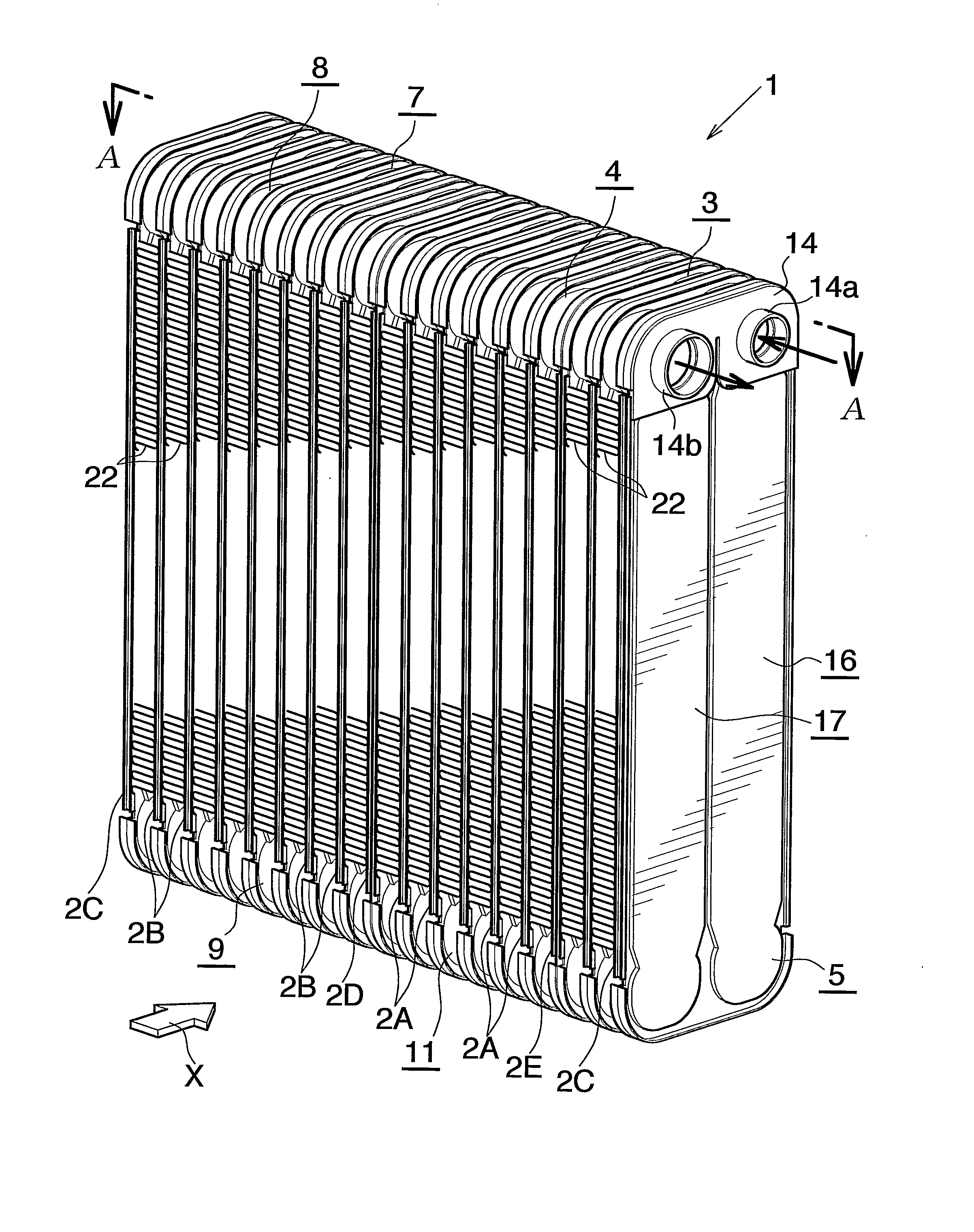
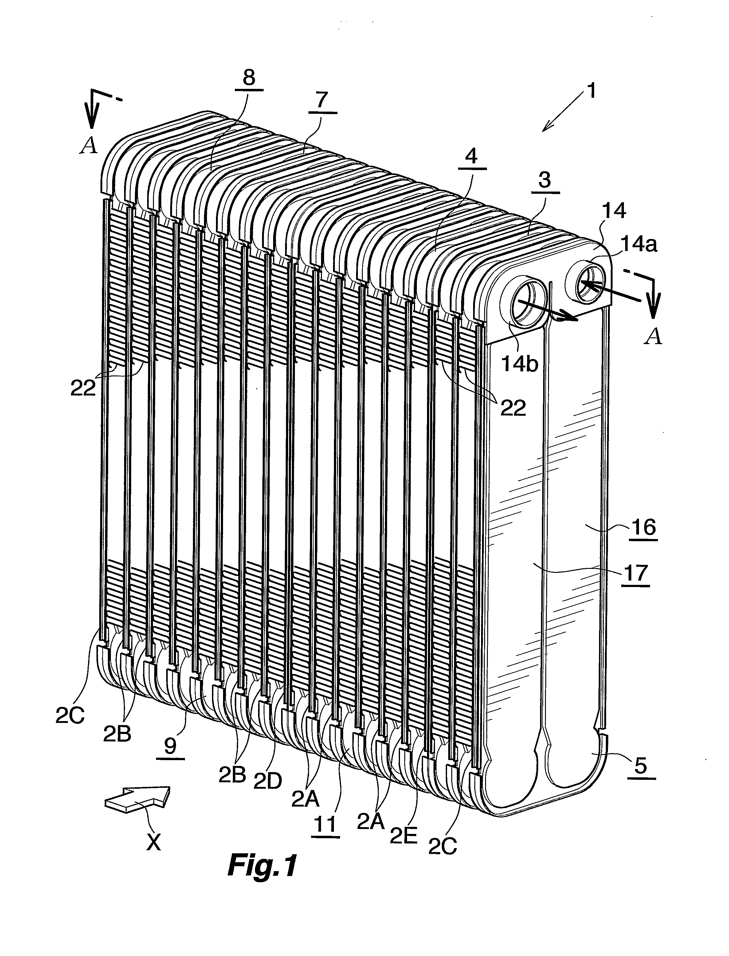
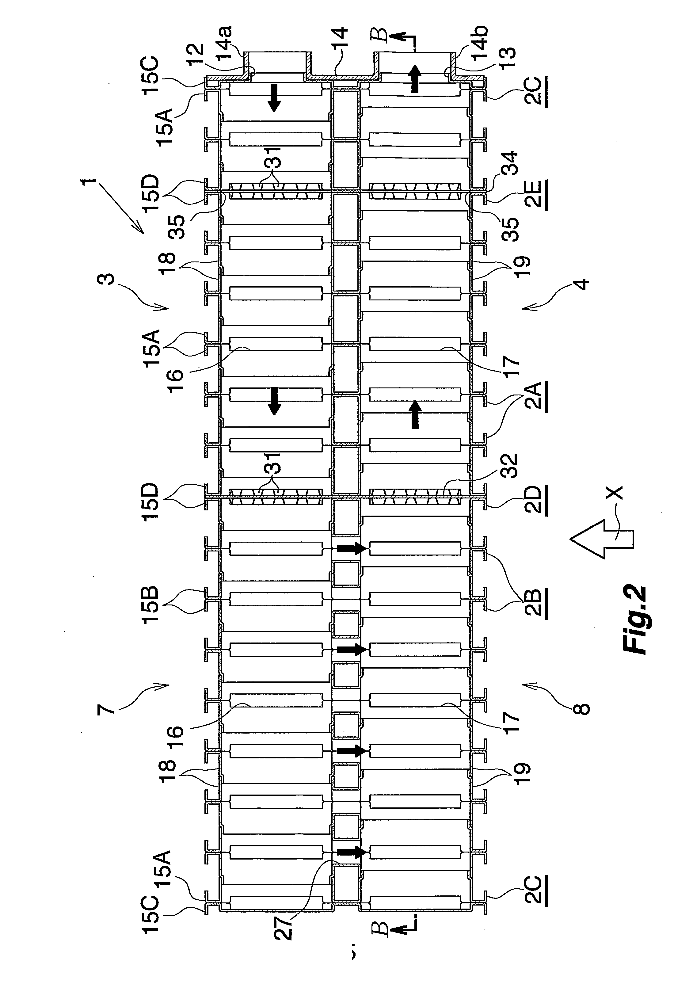
[0051] FIGS. 1 to 3 show the overall configuration of an evaporator of Embodiment 1; FIGS. 4 to 9 show the configurations of essential portions of the evaporator; and FIG. 10 shows the flow of refrigerant in the evaporator.

[0052] Referring to FIGS. 1 to 3, the evaporator (1) is configured such that a plurality of flat, hollow members (2A), (2B), (2C), (2D), and (2E) each having a vertically elongated rectangular shape are arranged in a laminated condition in the left-right direction and joined together while their widths extend in the front-rear direction (air flow direction). The evaporator (1) includes a refrigerant inlet header section (3) extending in the left-right direction; a refrigerant outlet header section (4) provided rearward (upstream, with respect to the air flow direction) of the refrigerant inlet header section (3) and extending in the left-right direction; a first intermediate header section (5) ...

Example

EMBODIMENT 2

[0069] The present embodiment is shown in FIGS. 11 to 15.

[0070]FIG. 11 shows the overall configuration of an evaporator of Embodiment 2; FIGS. 12 to 14 show the configurations of essential portions of the evaporator; and FIG. 15 shows the flow of refrigerant in the evaporator.

[0071] Referring to FIG. 11, the evaporator (40) is configured such that a plurality of flat, hollow members (41A), (41B), (41C), and (41D) each having a vertically elongated rectangular shape are arranged in a laminated condition in the left-right direction and joined together while their widths extend in the front-rear direction (air flow direction). The evaporator (40) includes a refrigerant inlet header section (42) extending in the left-right direction; a refrigerant outlet header section (43) provided continuous with and rightward of the refrigerant inlet header section (42) and extending in the left-right direction; a first intermediate header section (44) provided frontward (downstream, w...


PUM


Abstract

An evaporator implemented by a laminated heat exchanger includes a refrigerant inlet header section, a refrigerant outlet header section, and plural inter mediate header sections. A sixth intermediate header section includes a refrigerant channel allowing refrigerant flow in the longitudinal direction thereof and whose downstream end with respect to the refrigerant flow direction is closed, and causes refrigerant to dividedly flow into a plurality of refrigerant flow tube portions. Refrigerant that has flown into the refrigerant inlet header section from a refrigerant inlet flows into the refrigerant outlet header section through the refrigerant flow tube portions and through the intermediate header sections and flows out from a refrigerant outlet. A resistive plate portion within the sixth intermediate header section blocks the refrigerant channel thereof extending in the longitudinal direction thereof. A resistive hole in the resistive plate portion imparts resistance to refrigerant that flows through the refrigerant channel.

Description

CROSS REFERENCE TO RELATED APPLICATIONS [0001] This application is an application filed under 35 U.S.C. § 111(a) claiming the benefit pursuant to 35 U.S.C. § 119(e)(1) of the filing date of Provisional Application No. 60 / 609,831 filed Sep. 15, 2004 pursuant to 35 U.S.C. § 111(b).TECHNICAL FIELD [0002] The present invention relates to a laminated heat exchanger, and more particularly to a laminated heat exchanger used as an evaporator of a vehicle air conditioner, which is a refrigeration cycle on board a vehicle. [0003] Herein and in the appended claims, the upper, lower, left-hand, and right-hand sides of FIGS. 1, 3, and 11 will be referred to as “upper,”“lower,”“left,” and “right,” respectively. The downstream side of flow (represented by arrow X in FIGS. 1 and 11) of air is referred to as the “front,” and the opposite side as the “rear.”BACKGROUND ART [0004] A laminated heat exchanger that is conventionally used widely as an evaporator of a vehicle air conditioner includes a plur...

Claims


Application Information

Patent Timeline
IPC IPC(8): F28D1/04F25B39/02
CPCF25B39/022F28D2021/0085F28D1/0341F28D1/0333
Inventor MORI, DAISUKEHIGASHIYAMA, NAOHISA
Owner SHOWA DENKO KK
Why Eureka
Try Eureka