

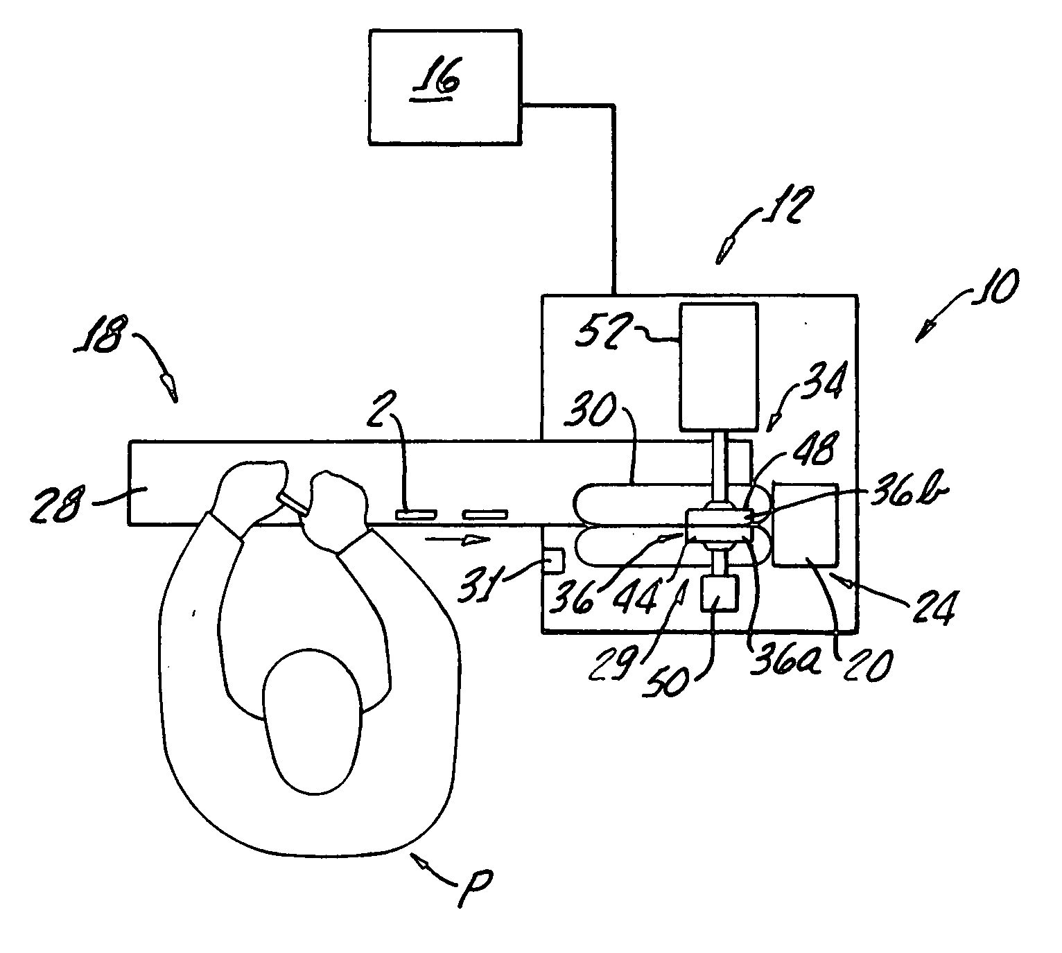
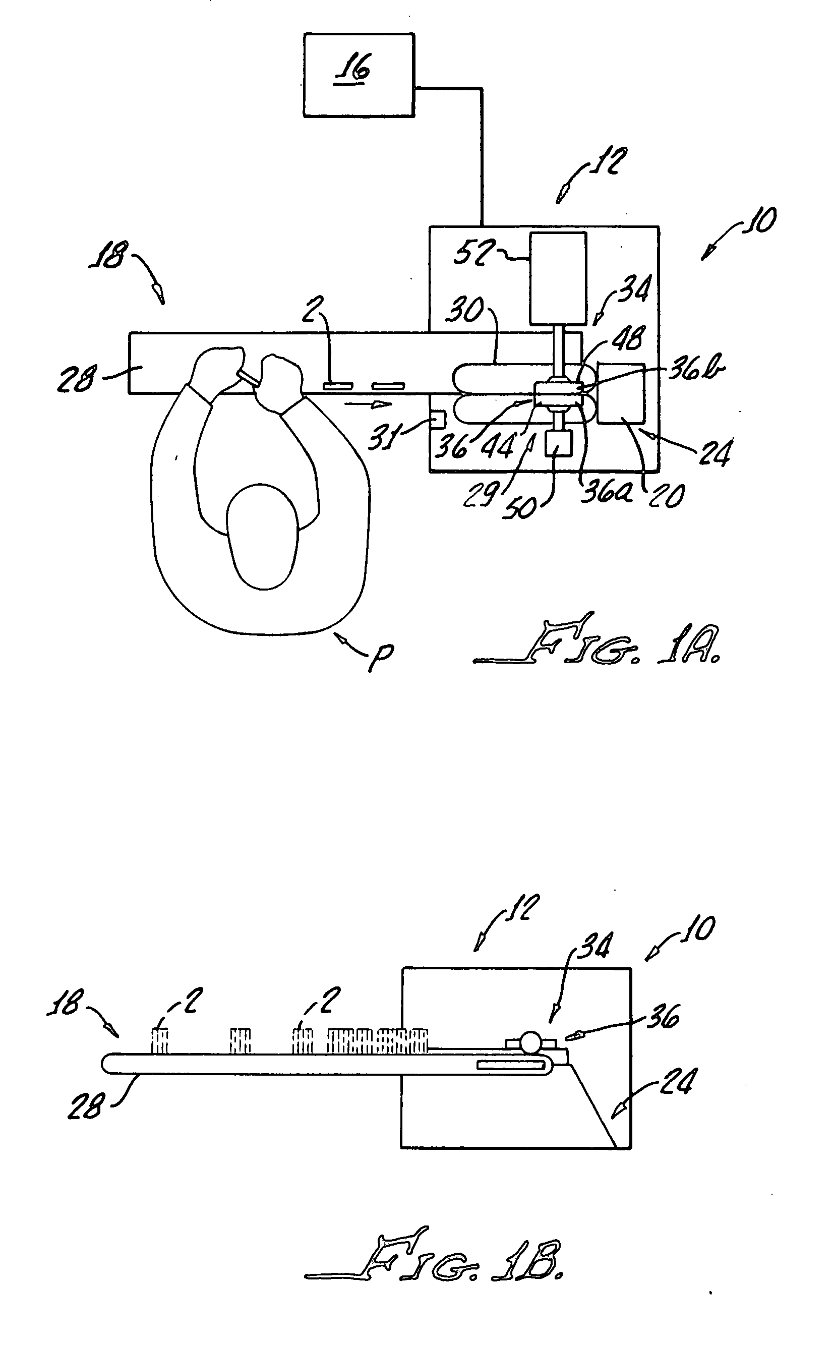
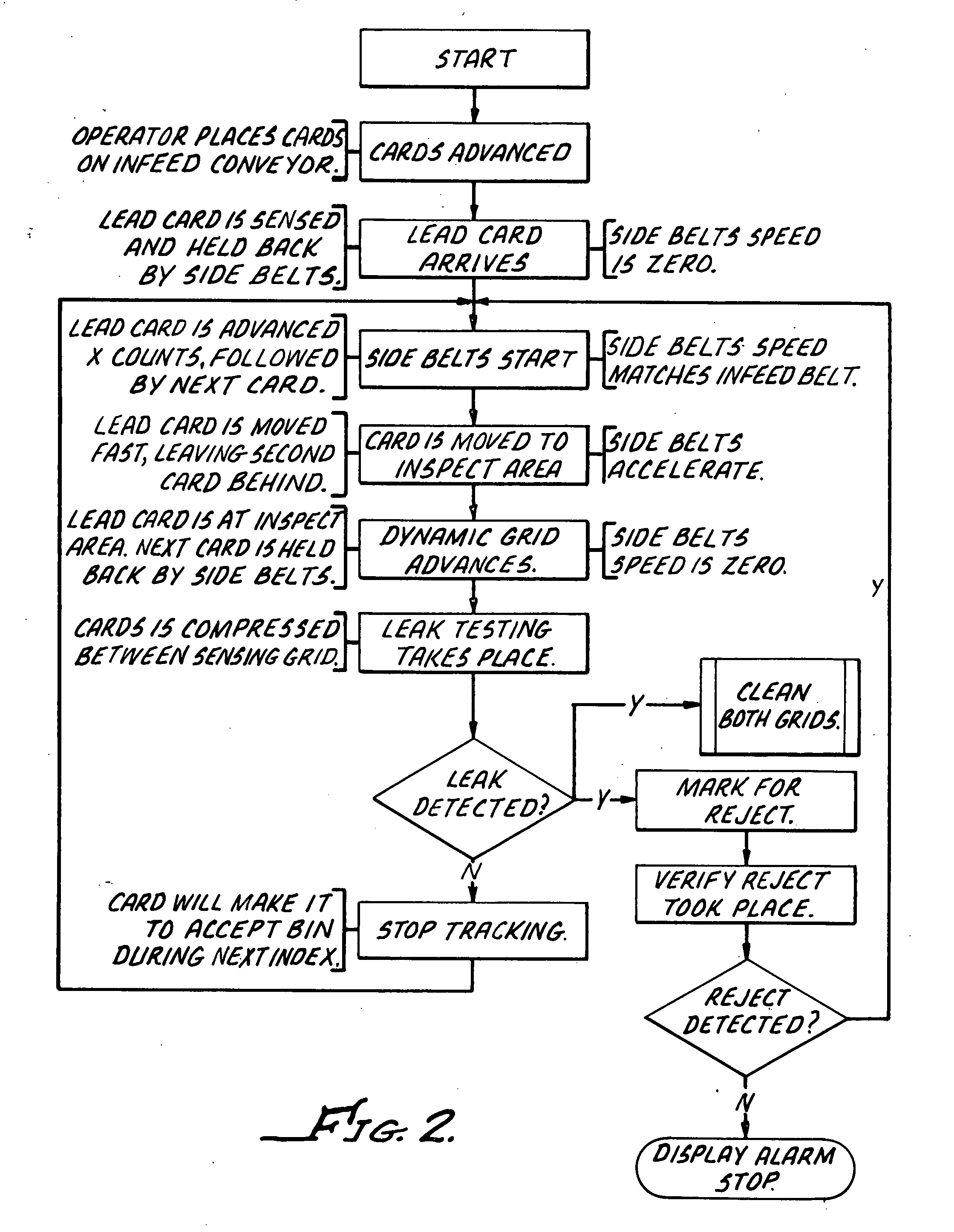
Ampoule card leak detector assembly
a leak detector and ampoule card technology, applied in the field of pharmaceutical products, can solve the problem of not allowing visually visible escaping of fluid, and achieve the effect of soft and flexibl
- Summary
- Abstract
- Description
- Claims
- Application Information
AI Technical Summary
Benefits of technology
Problems solved by technology
Method used
Image

Examples
example 1
[0044] A test is conducted to determine an appropriate amount of compression to be applied to ampoule packages to cause the ampoules to leak from a preexisting structural breach in the ampoule, without causing damage (e.g. breaking or bursting) of a non-defective ampoule.
[0045] For purposes of this specific Example, Package 1, Package 2, Package 3 and Package 4 are different types of ampoule packages which contain liquid solutions. Package 1 and Package 2 are standardized vials each containing a different pharmaceutical solution. Package 3 and Package 4 are vials having “twist-off” style caps. Package 3 and Package 4 contain different pharmaceutical solutions.
[0046] These four Packages are to be tested by compressing several packages representing each Package from an original thickness of about ⅓″ to ⅜″ to a thickness of about ⅛″.
[0047] The force required to reach this level of compression without breaking the packages can be calculated. For each of Packages 1 to 4, ten ampoule p...
example 2
Using Electrical Properties of Solution for Leak Testing
[0056] This example is provided to describe a test that can be used to achieve proper calibration of the electrical components and circuitry for use in the present systems and methods. It is also provided to demonstrate the reliability of the present systems in being capable of detecting leaks using the electrical properties of certain solutions.
[0057] For purposes of this specific Example, Product 1, Product 2 and Product 3 are three different types of water-based pharmaceutical solutions that are packaged in ampoule packages for testing using the present systems and methods, for example, system 10.
[0058] As explained elsewhere herein, the present systems and methods use the electrical properties of the solution in the packages to detect the presence of the solution outside the compressed ampoule, for example, on a sensing grid.
[0059] The electronic amplifier connected to the sensing grids is constantly monitoring resistan...
PUM
 Abstract
Description
Claims
Application Information