
Twisting device for knitwear

A technology of twisting device and needle textiles, which is applied in the direction of textiles and papermaking, and can solve the problems of unguaranteed service life of the transmission device, low output power of the twisting machine, failure to stop in time, etc., and achieves simple structure, long belt life, The effect of easy operation

Active Publication Date: 2018-07-06
SUZHOU YUANLIAN SCI & TECH PIONEER PARK MANAGEMENT CO LTD
View PDF5 Cites 0 Cited by
  • Summary
  • Abstract
  • Description
  • Claims
  • Application Information

AI Technical Summary

Problems solved by technology

[0002] The twisting process belongs to post-spinning. Textile machinery is divided into pre-spinning and post-spinning. Front-spinning is a spinning machine, and post-spinning is a texturing machine. The silk spun out of the front cannot be used because the twist is not enough, that is, the elasticity is not enough. The device that needs to be twisted by the texturing process is called a twister, which is mainly used in the texturing machine industry and is called the heart of the texturing machine; the existing twisting device has certain disadvantages in use. First, the twisting machine The output power is low, the twisting efficiency needs to be further improved, and the pressure on the rollers is too high when the power is increased, and the life of the transmission device cannot be guaranteed. Caused damage to the rollers, did not stop working or replace the rollers in time, caused greater losses, and had a certain impact on people's use. Therefore, we propose a twisting device for needled textiles

Method used

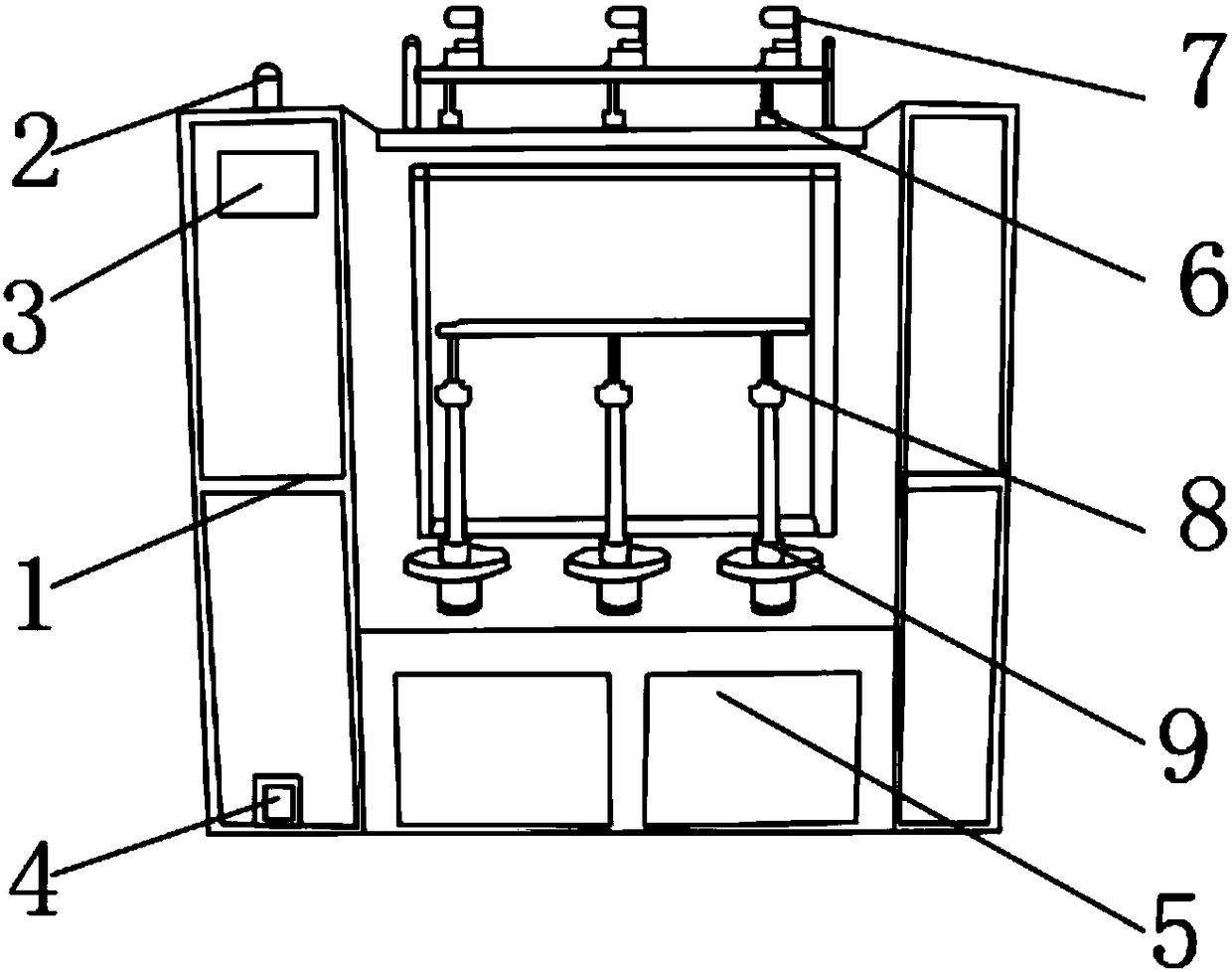

Image

  • Twisting device for knitwear
  • Twisting device for knitwear
  • Twisting device for knitwear

Examples


Embodiment Construction

[0018] In order to make the technical means, creative features, goals and effects achieved by the present invention easy to understand, the present invention will be further described below in conjunction with specific embodiments.

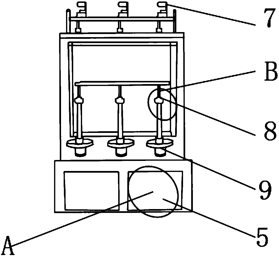
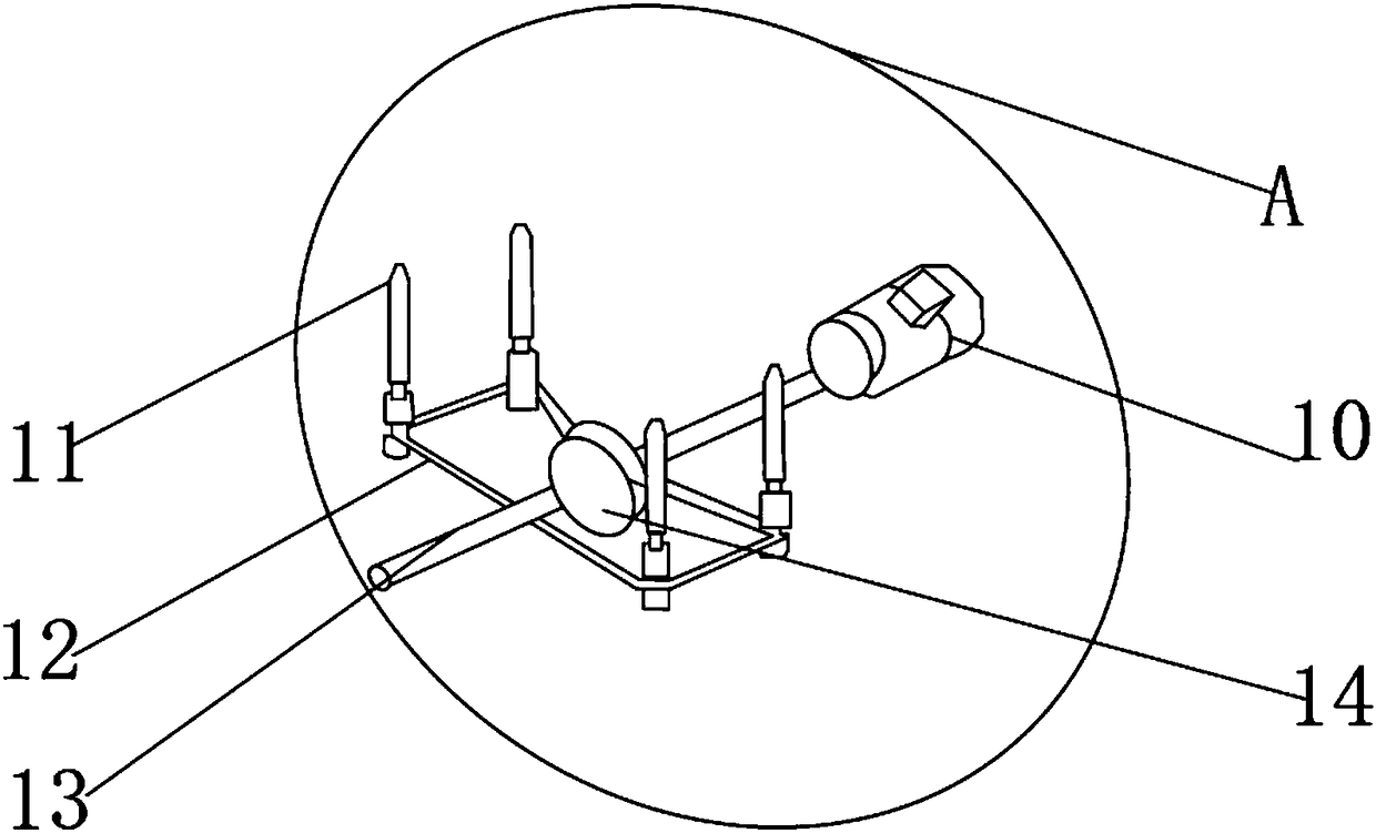
[0019] Such as Figure 1-5 As shown, a twisting device for needled textiles includes a twisting machine main body 1, an alarm 2 is fixedly installed on the top of the twisting machine main body 1, and an upper end of the twisting machine main body 1 is arranged below the alarm 2 Control panel 3, the outer surface of the lower end of the twisting machine main body 1 is provided with a power switch 4, and the lower end of the twisting machine main body 1 is fixedly installed with a transmission box 5 near the power switch 4 side, and the upper end of the twisting machine main body 1 is fixedly installed with The clamping plate 6, and the upper surface of the clamping plate 6 is fixedly installed with a wire passing plate 7, the middle of the twistin...


PUM


Abstract

The invention discloses a twisting device for knitwear. The twisting device comprises a twisting machine body. An alarm is fixedly installed at the top end of the twisting machine body. A control panel is arranged on the portion, close to the lower portion of the alarm, of the upper end of the twisting machine body, a power switch is arranged on the outer surface of the lower end of the twisting machine body, transmission boxes are fixedly installed on the portion, close to one side of the power switch, of the lower end of the twisting machine body, thread brackets are fixedly installed at theupper end of the twisting machine body, thread pass plates are fixedly installed on the upper surfaces of the thread brackets, and rollers are fixedly installed in the middle of the twisting machinebody. The twisting device for the knitwear is provided with a diesel engine, a flat belt and torque sensors, output power can be increased, the twisting efficiency can be improved, the pressure on therollers can be reduced, the transmission service life of a twisting machine can be prolonged, the torque of the rollers can be accurately measured in time, the torque of the rollers is prevented fromexceeding a reasonable range,and better use prospects are achieved.

Description

technical field [0001] The invention relates to the field of twisting devices, in particular to a twisting device for knitted textiles. Background technique [0002] The twisting process belongs to post-spinning. Textile machinery is divided into pre-spinning and post-spinning. Front-spinning is a spinning machine, and post-spinning is a texturing machine. The silk spun out of the front cannot be used because the twist is not enough, that is, the elasticity is not enough. The device that needs to be twisted by the texturing process is called a twister, which is mainly used in the texturing machine industry and is called the heart of the texturing machine; the existing twisting device has certain disadvantages in use. First, the twisting machine The output power is low, the twisting efficiency needs to be further improved, and the pressure on the rollers is too high when the power is increased, and the life of the transmission device cannot be guaranteed. The roller is damag...

Claims


Application Information

Patent Timeline
Patent Type & Authority Applications(China)
IPC IPC(8): D01H13/32D01H7/00
CPCD01H7/00D01H13/32
Inventor 金惠如
Owner SUZHOU YUANLIAN SCI & TECH PIONEER PARK MANAGEMENT CO LTD
Learn More