
Batch Processing Platform For ALD and CVD

a technology of cvd and processing platform, which is applied in the direction of conveyor parts, transportation and packaging, coatings, etc., can solve the problems of reducing the efficiency of the process, and reducing the efficiency of the system, so as to achieve the effect of reducing the footprint and high throughpu

Inactive Publication Date: 2007-12-27
APPLIED MATERIALS INC
View PDF23 Cites 39 Cited by
  • Summary
  • Abstract
  • Description
  • Claims
  • Application Information

AI Technical Summary

Benefits of technology

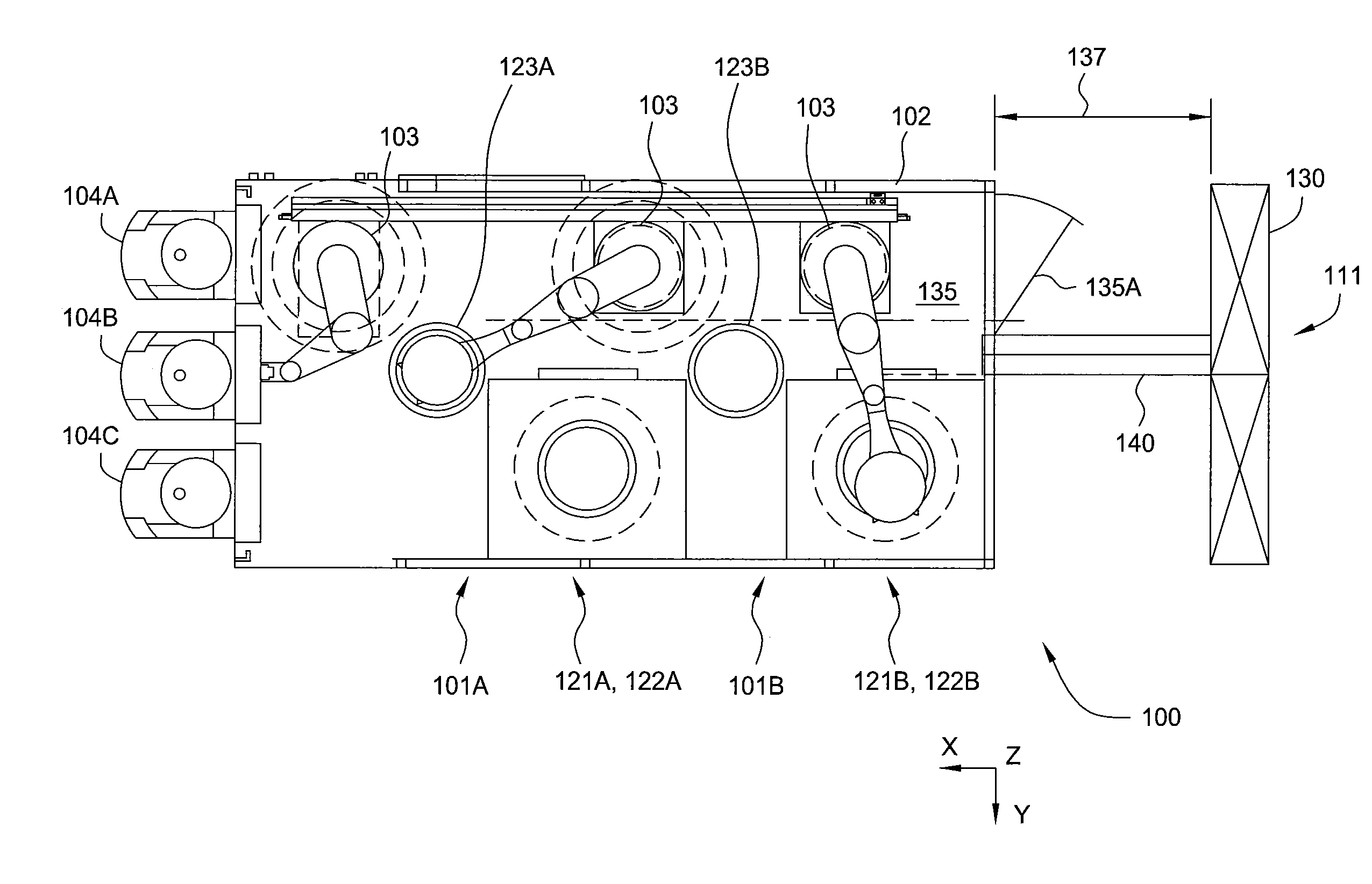
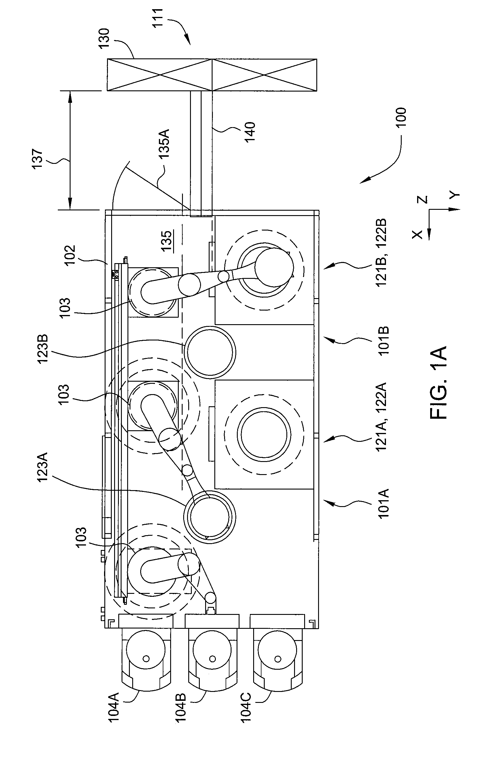
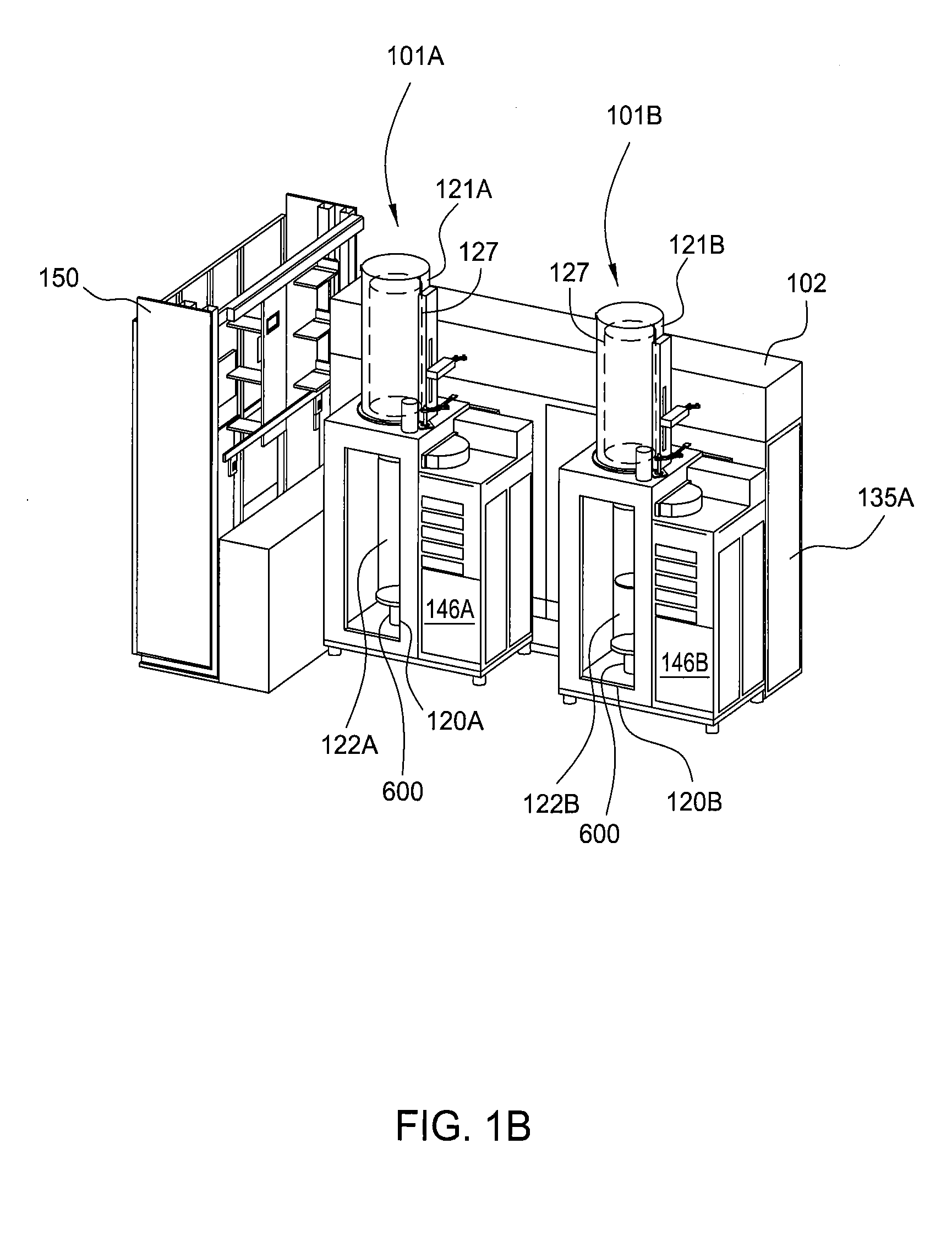
[0008]Embodiments of the present invention provide a batch processing platform used for ALD or CVD processing of substrates with minimized footprint and high throughput. In one embodiment, the processing platform comprises an atmospheric transfer region, at least one batch processing chamber with a buffer chamber and staging platform, and a transfer robot disposed in the transfer region wherein the transfer robot has at least one substrate transfer arm that comprises multiple substrate handling blades. The transfer robot may be adapted to transfer substrates between a proce

Problems solved by technology

Hence, although a substrate processing platform may be relatively small, if it requires access from all sides for operation and maintenance, the system's effective footprint may still be prohibitively large.
To meet these tighter process requirements, the industry has developed a host of new processes which meet the tighter process window requirements, but these processes often take a longer time to complete.
The biggest drawback with ALD techniques is that the deposition rate is much lower than typical CVD techniques by at least an order of magnitude.
While forced to choose such processes due to device performance requirements, the cost to fabricate the devices in a conventional single substrate processing chamber will increase due to the low substrate throughput.

Method used


Image

  • Batch Processing Platform For ALD and CVD
  • Batch Processing Platform For ALD and CVD
  • Batch Processing Platform For ALD and CVD

Examples


Embodiment Construction

[0037]A batch processing platform for ALD and CVD applications is provided, wherein throughput is maximized and footprint is minimized. In one embodiment, throughput is improved by using a multiple arm robot to transfer substrates. In another embodiment, a cassette handler robot is used to transfer entire cassettes to improve throughput.

Multiple Arm Robot Platform

[0038]In this embodiment, a robot with multiple arms transfers substrates between a staging cassette and a processing cassette using an arm configured with multiple blades to reduce transfer times therebetween. Because a processing chamber is idle during substrate transfers, it is beneficial for system throughput to minimize the time required for transferring substrates into and out of a processing cassette. The robot also transfers substrates between a substrate transport pod and the staging cassette using another arm configured with a single blade to accommodate the difference in substrate spacing between the pod and the ...


PUM

PropertyMeasurementUnit
Pressureaaaaaaaaaa
Volumeaaaaaaaaaa

Abstract

A batch processing platform used for ALD or CVD processing is configured for high throughput and minimal footprint. In one embodiment, the processing platform comprises an atmospheric transfer region, at least one batch processing chamber with a buffer chamber and staging platform, and a transfer robot disposed in the transfer region wherein the transfer robot has at least one substrate transfer arm that comprises multiple substrate handling blades. The platform may include two batch processing chambers configured with a service aisle disposed therebetween to provide necessary service access to the transfer robot and the deposition stations. In another embodiment, the processing platform comprises at least one batch processing chamber, a substrate transfer robot that is adapted to transfer substrates between a FOUP and a processing cassette, and a cassette transfer region containing a cassette handler robot. The cassette handler robot may be a linear actuator or a rotary table.

Description

BACKGROUND OF THE INVENTION[0001]1. Field of the Invention[0002]Embodiments of the present invention generally relate to an apparatus for processing substrates. More particularly, the invention relates to a batch processing platform for performing atomic layer deposition (ALD) and chemical vapor deposition (CVD) on substrates.[0003]2. Description of the Related Art[0004]The process of forming semiconductor devices is commonly conducted in substrate processing platforms containing multiple chambers. In some instances, the purpose of a multi-chamber processing platform or cluster tool is to perform two or more processes on a substrate sequentially in a controlled environment. In other instances, however, a multiple chamber processing platform may only perform a single processing step on substrates; the additional chambers are intended to maximize the rate at which substrates are processed by the platform. In the latter case, the process performed on substrates is typically a batch pro...

Claims


Application Information

Patent Timeline
IPC IPC(8): C23C16/00
CPCC23C16/4583C23C16/54H01L21/67173Y10S414/14H01L21/67757H01L21/67769H01L21/67742
Inventor WEBB, AARONBRAILOVE, ADAMYUDOVSKY, JOSEPHMERRY, NIRCONSTANT, ANDREWQUILES, EFRAINRICE, MICHAEL R.ROSEN, GARY J.SHAH, VINAY K.
Owner APPLIED MATERIALS INC
Learn More