PV Module Mounting and Support Assembly and Installation

a technology for pv modules and support assemblies, applied in the direction of connection contact member materials, lighting and heating apparatuses, light radiation electric generators, etc., can solve the problems of difficult to tell if adequate waterproofing has been achieved, add significantly to installation time, etc., to reduce the number of parts, reduce the cost and installation complexity, and reduce the effect of installation tim

Inactive Publication Date: 2007-12-27
SUNPOWER CORPORATION
View PDF19 Cites 80 Cited by
  • Summary
  • Abstract
  • Description
  • Claims
  • Application Information

AI Technical Summary

Benefits of technology

[0009] An advantage of the invention is that it is suitable for use with a number of different conventionally designed PV modules. The PV modules do not need any special hold down or attachment structures for use with various examples of this invention. In addition, the size of the modules does not depend on the spacing of the joists or other structure supporting the deck. Installation typically does not require access to an attic area for installation of blocking (which is not needed) or inspections. Some examples of the invention significantly reduce part count over conventional mounting systems, for example by eliminating the need for mounting rails, which reduces cost and installation complexity. In addition, some examples help to significantly reduce installation time, which also reduces cost. Additionally, some examples allow very low profile securement of the PV modules to the roof or other support structure. In some examples the PV modules can be mounted nearly flush to the support structure, consistent with proper airflow for cooling, which improves the aesthetics significantly. The region beneath the PV module can typically be fluidly coupled to the region above the module. Wind tunnel tests may be carried out to determine the parameters that would result in, for example, pressure equalization between the upper and lower surfaces, thus providing for reduced loads on the PV modules under different wind conditions. Wind loading on photovoltaic modules is discussed in more detail in U.S. patent application Ser. No. 10 / 922,117 filed Aug. 19, 2004 and entitled PV Wind Performance Enhancing Methods and Apparatus, US Patent Publication Number US-2005-0126621-A1 published Jun. 16, 2005. In some examples the mounting structure can incorporate both a hold down (mounting) function and an electrical grounding function to substantially eliminate the need for additional grounding structure. Some examples of the PV mounting and support assemblies permit adjacent PV modules to be placed relatively close to one another. This not only improves aesthetics but also increases the energy output for a given area of the roof or other support structure. By positioning deck-penetrating fasteners beneath the PV modules, uplift forces are essentially tension only; this is in contrast with some conventional PV module hold down structures in which the deck-penetrating fasteners are laterally offset from the PV modules resulting in both tension and bending forces on the fasteners.

Problems solved by technology

Reasons for using the vertical stanchions and a lateral rails approach include: PV modules are not typically designed in convenient widths relative to joist spacing, not all PV modules have geometries amenable to direct-deck mounting, and the racks are designed to accommodate generally any PV module.
Because of the size of these larger holes and the configuration of the module, it is often difficult to tell if adequate waterproofing has been achieved.
If blocking is used, the process of installing blocking involves extensive work in the attic which adds significantly to installation time.

Method used


Image

  • PV Module Mounting and Support Assembly and Installation
  • PV Module Mounting and Support Assembly and Installation
  • PV Module Mounting and Support Assembly and Installation

Examples


Embodiment Construction

[0026] The following description will typically be with reference to specific structural embodiments and methods. It is to be understood that there is no intention to limit the invention to the specifically disclosed embodiments and methods but that the invention may be practiced using other features, elements, methods and embodiments. Preferred embodiments are described to illustrate the present invention, not to limit its scope, which is defined by the claims. Those of ordinary skill in the art will recognize a variety of equivalent variations on the description that follows. Like elements in various embodiments are commonly referred to with like reference numerals.

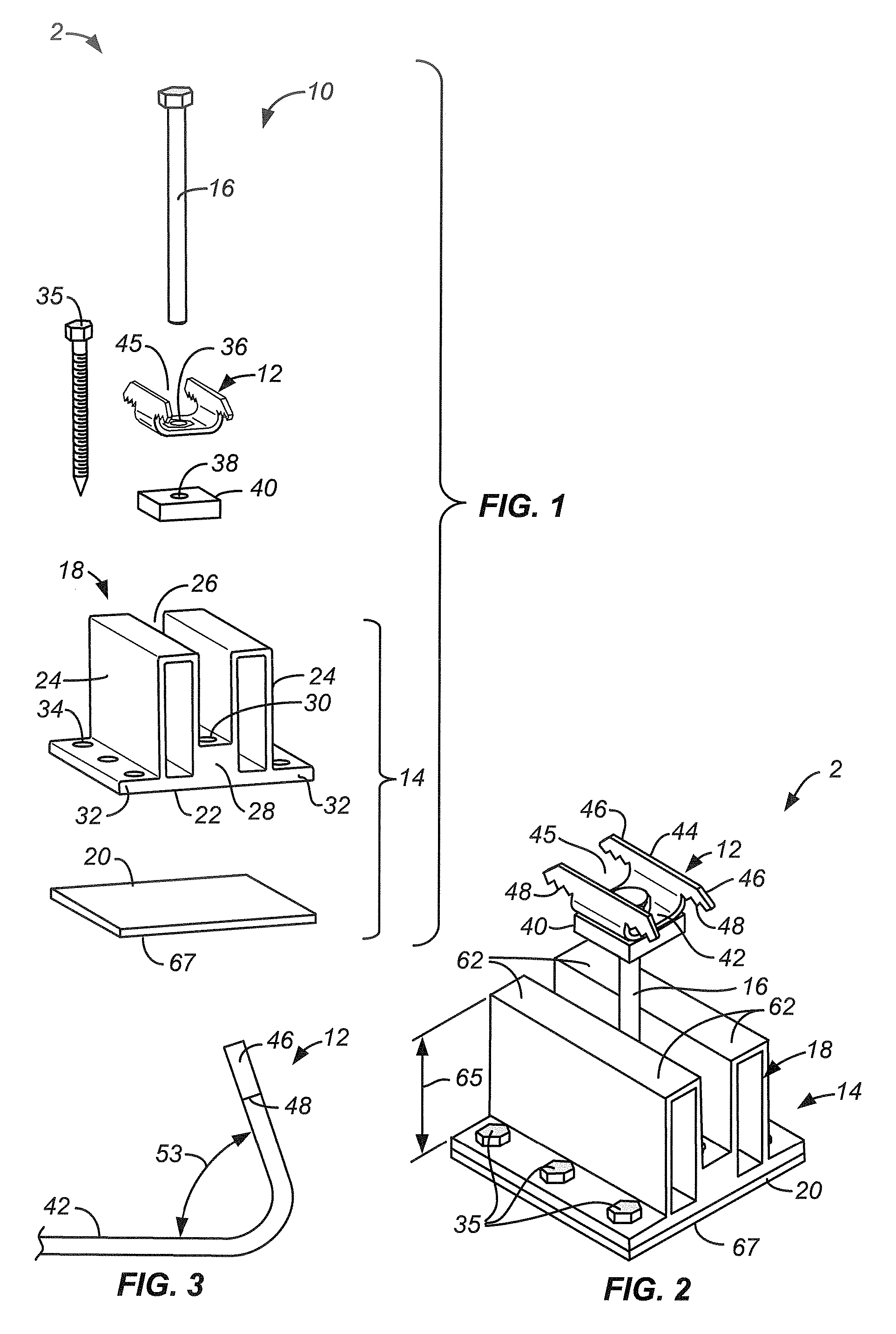
[0027]FIG. 1 is an exploded isometric view of one example of a PV mounting and support assembly 2 made according to the invention. Assembly 2 includes a clip assembly 10 and a base 14. Clip assembly 10 includes a clip 12 secured to base 14 by a bolt 16. Base 14 includes a base body 18, typically of extruded aluminum or...


PUM


Abstract

In some examples a PV module mounting and support assembly includes a base mountable to the deck, a deck-penetrating fastener for securing the base to the deck, and PV module mounting hardware. The PV module mounting hardware is used to secure an edge of a PV module on a PV module-support surface of the base with the edge of the PV module spaced apart from the deck. Flashing may be used between the lower surface and the deck. In some examples an internal PV mounting and support assembly is used to engage an internal lip of the PV module frame.

Description

CROSS-REFERENCE TO OTHER APPLICATIONS [0001] This application claims the benefit of provisional patent application No. 60 / 821,869 filed 9 Aug. 2006, Attorney Docket number PWRL 1045-1. This application is also a continuation in part of U.S. patent application Ser. No. 11 / 681,972 filed 5 Mar. 2007, Attorney Docket number PWRL 1044-2, which application claims the benefit of provisional patent application No. 60 / 780,819 filed on 9 Mar. 2006, attorney docket number PWRL 1044-1 and provisional patent application No. 60 / 821,869 filed on 9 Aug. 2006, attorney docket number PWRL 1045-1, the disclosures of which are incorporated by reference. This application is related to U.S. patent application Ser. No. ______ filed on the same day as this application, entitled PV Module Mounting Method and Mounting Assembly, attorney docket PWRL 1045-3.STATE SPONSORED RESEARCH OR DEVELOPMENT [0002] This invention was made with State of California support under California Commission Agreement Number 500-04...

Claims


Application Information

Patent Timeline
Patent Type & Authority Applications(United States)
IPC IPC(8): H02N6/00A44B99/00
CPCF24J2/5245F24J2/5258F24J2002/5294H02S20/00Y02E10/47Y02E10/50H01R4/64F24S25/20F24S25/61F24S25/634F24S25/636F24S2025/021F24S2025/6008H02S20/23Y02B10/10Y10T24/44H01R13/73
Inventor LENOX, CARL J. S.JOHNSON, KURT M.
Owner SUNPOWER CORPORATION
Why Eureka
Try Eureka