Heat spreader with composite micro-structure

a technology of composite microstructure and heat spreader, which is applied in indirect heat exchangers, heat exchange apparatus, lighting and heating apparatus, etc., can solve the problems of ineffective capillary, difficult to enhance capillary and reduce flowing resistance at the same time, etc., to achieve the effect of reducing flowing resistance and enhancing capillary

Inactive Publication Date: 2007-12-27
TAIWAN MICROLOOPS CORP
View PDF11 Cites 58 Cited by
  • Summary
  • Abstract
  • Description
  • Claims
  • Application Information

AI Technical Summary

Benefits of technology

[0010] The primary objective of this invention is to provide a heat spreader with a novel composite micro-structure. The heat spreader of the present invention can not only enhance the capi...

Problems solved by technology

However, because the heat pipe can not work independently, another flat type heat pipe, also known as “heat spreaders,” has been developed.
Conventionally, it is difficult to both enhance the capillarity and reduce the flowing resistance at the same time.
When a ...

Method used


Image

  • Heat spreader with composite micro-structure
  • Heat spreader with composite micro-structure
  • Heat spreader with composite micro-structure

Examples


first embodiment

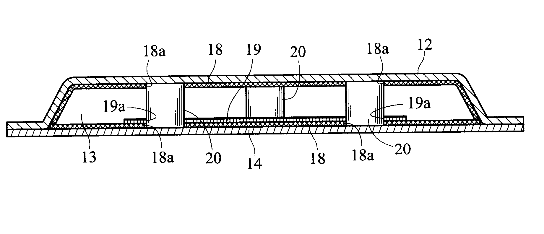
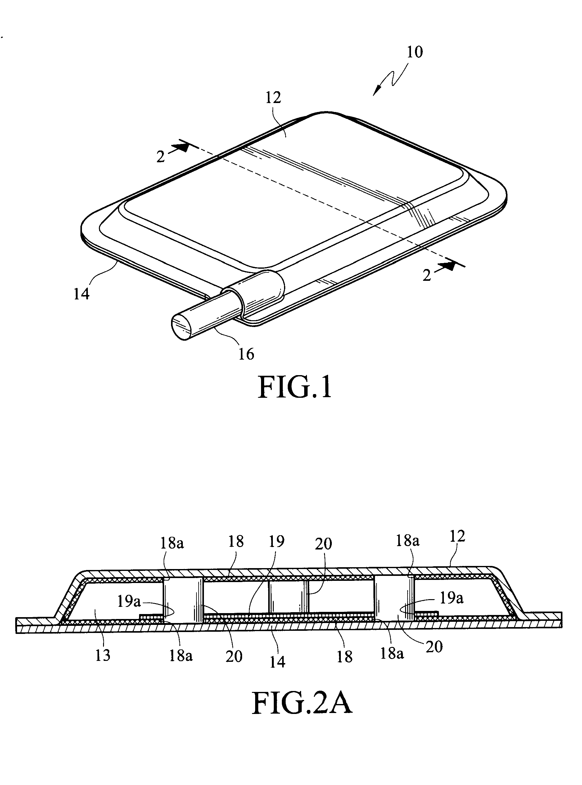
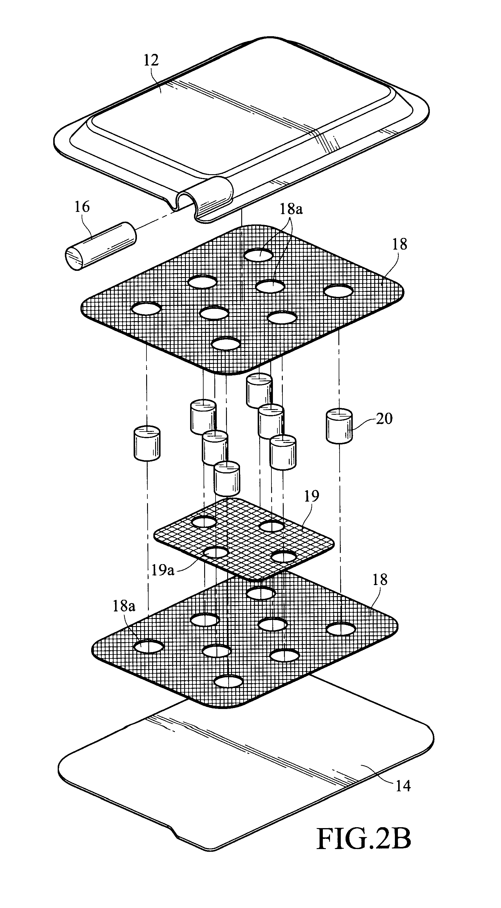
[0027] the micro-structure layer formed on the inner surface of casing is shown in FIG. 2A and FIG. 2B. The micro-structure which is made of a copper mesh in the embodiments thereinafter can also be made of any other suitable metal, such as aluminum, without any changes to the structure. The copper meshes hereinafter are disclosed for illustration convenience.

[0028] The first metallic mesh 18, or namely, the first structure layer, is substantially formed on all the surfaces of the chamber 13 as a capillary structure for the working fluid circulating therein. The first metallic mesh 18 can be applied using various conventional manufacturing processes, such as welding or diffusion bonding, to attach onto the surface. In the present invention, diffusion bonding is preferably used to form the first structure layer. The second metallic mesh 19, or namely, the second structure layer, is disposed on the first metallic mesh 18 on the lower cover 14 in this embodiment. The second metallic me...

second embodiment

[0034] In the second embodiment, an opening 18b corresponding to the vaporization area is formed on the first metallic mesh 18 to fit the second metallic mesh 19. The second metallic mesh 19 can be embedded within the opening 18b and comes into contact with the first metallic mesh 18 at the periphery. Furthermore, the meshes 18 and 19 can both attach onto the inner surface of the lower cover 14. In other words, the first metallic mesh 18 and the second metallic mesh 19 are disposed on the same surface to ensure transportation (as shown in FIG. 3A).

[0035] In the embodiments as shown in FIGS. 2A, 2B, 3A and 3B, a single mesh 19 is disclosed. Certainly, a plurality of meshes can be applied in the present invention. As shown in FIG. 4 and FIG. 5, two meshes 19′a and 19′b are stacked to form the second metallic mesh 19′. In this case, the meshes 19′a and 19′b can have differently or similarly sized cavities. Preferably, the meshes 19′a and 19′b should be stacked at different orientations...


PUM


Abstract

A heat spreader comprising a casing, a micro-structure layer, a support device, and a working fluid is provided. The casing has an inner surface and is defined by a sealed chamber where the working fluid circulates therein. The micro-structure layer is formed on the inner surface of the casing, wherein the micro-structure layer comprises a first structure layer which is formed by the first metallic mesh. Specifically, the first metallic mesh forms the first structure layer on the inner surface through diffusion bonding so that the working fluid can circulate within the micro-structure layer by capillary action. In addition, the support device is disposed in the sealed chamber for supporting the casing. Thus, a heat spreader with a composite micro-structure can not only enhance the capillarity but also reduce the flowing resistance during operation.

Description

[0001] This application claims the befits of priority based on Taiwan Patent Application No. 095206851 filed on Apr. 21, 2006; the disclosures of which are incorporated by reference herein in their entirety. RELATED APPLICATIONS [0002] Not applicable. TECHNICAL FIELD [0003] The present invention relates to a heat spreader. In particular, the invention relates to a heat spreader with a composite micro-structure. BACKGROUND Descriptions of the Related Art [0004] In current electronic apparatuses, such as personal computers, communication devices, or thin-film-transistor liquid crystal displays, many electronic components that may generate heat during operation are used. Inevitably, as operation speed is increased, more heat is generated from the electronic apparatus. Therefore, it is important to prevent the electronic apparatus from overheating so that efficiency is not thereby, reduced. Thus, various cooling devices and methods for use in electronic apparatuses have been developed. ...

Claims


Application Information

Patent Timeline
IPC IPC(8): F28D15/00
CPCF28D15/046F28D15/0233
Inventor SU, CHERNG-YUHLEE, KUO-YINGLIIN, CHIEN-HUNG
Owner TAIWAN MICROLOOPS CORP
Why Eureka
Try Eureka