Multi-band circular polarity elliptical horn antenna
a circular polarity, elliptical horn technology, applied in waveguide horns, antennas, electrical devices, etc., can solve the problems of poor cross polarization performance, and difficult to achieve good circular polarity cross polarization isolation, etc., to achieve good circular polarity performan
- Summary
- Abstract
- Description
- Claims
- Application Information
AI Technical Summary
Benefits of technology
Problems solved by technology
Method used
Image
Examples
embodiment 400
[0095] The antenna feed horn 600 described with reference to FIGS. 6A-B, is a broadband high performance elliptical beam circular polarity design that employs an elliptical beam horn deliberately designed to work in conjunction with an additional opposite slope phase differential section to greatly improve performance over very broad frequency bands as shown in FIG. 6C. To enable this embodiment, the inventor recognized that the phase differential introduced by most circular polarizers and the elliptical horn 400 (FIGS. 4A-B) are not a constant over the desired bandwidth. It is generally sloped versus frequency as shown in FIG. 7. So for the elliptical horn of embodiment 400, and for most circular polarity polarizers, the desired 90 degree total phase differential needed for complete CP conversion only occurs at a single frequency. This slope in phase differential versus frequency fundamentally limits the cross polarization performance over a wide bandwidth. For this embodiment, the...
embodiment 500
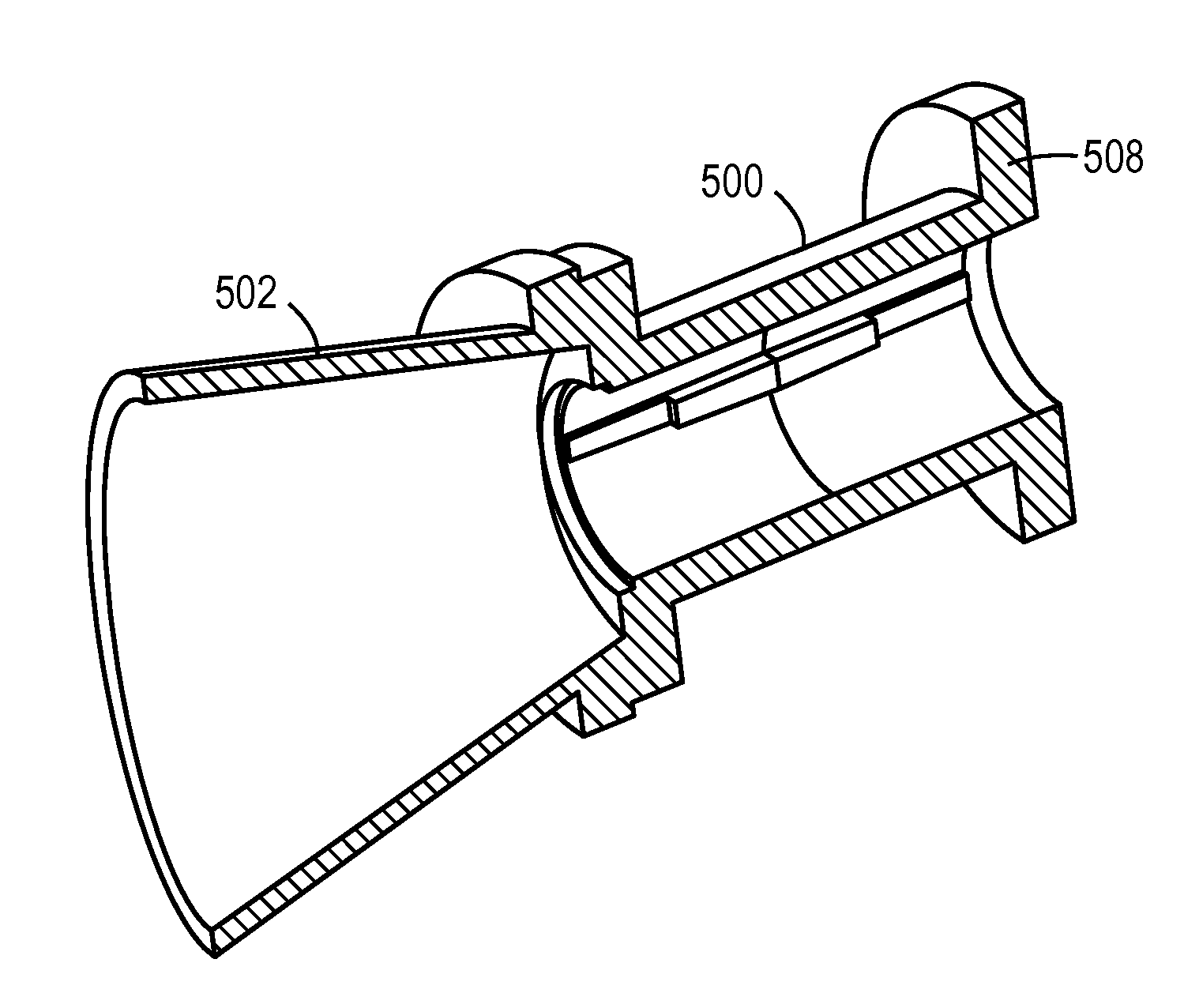
[0101] The embodiment 500 shown FIGS. 5A-C is an elliptical beam circular polarity design that employs an elliptical beam horn with an additive phase differential section to achieve CP polarization conversion over modest bandwidths. For this embodiment, the inventor recognized that the phase differential “X” introduced between orthogonal linear components by the elliptical horn is often something other than 90 degrees (X=35 degrees for example) and that an additive phase differential section can be added to provide the additional phase differential Y (Y=55 degrees in this example) to obtain a total phase differential of 90 degrees or an odd integer multiple of 90 degrees ( . . . −630 degrees, −450 degrees, −270 degrees, −90 degrees, 90 degrees, 270 degrees, 450 degrees, 630 degrees . . . ) near center band. The nominal phase differentials from the horn transition section and the additive phase differential section are indeed additive or in the same direction (if one introduces a pha...
third embodiment
[0119] For antenna feed horn 1100, the total length of the horn, phase compensation section and conventional polarizer will in general be slightly longer and more difficult to make than the antenna feed horn 400 (FIGS. 4A-B) and significantly longer and moderately more difficult to make than the antenna feed horn 600 (FIGS. 6A-B). However the phase compensation section of this third embodiment could be easily and cost effectively integrated into the horn casting.
[0120] Referring now to FIGS. 10A-B and 12A-C, all of these embodiments can be used in single-feed or multi-feed reflector systems where the feeds are mounted separately or integrated in one or more housings that are mounted on an antenna dish to generate multiple receive and / or transmit beams for receiving from or transmitting to multiple nominal sources and / or receiver locations such as multiple satellite locations that can be separated by as little one degrees and as much as 180 degrees. FIGS. 3A-D illustrate a system tha...
PUM
 Abstract
Description
Claims
Application Information
 - R&D
- Intellectual Property
- Life Sciences
- Materials
- Tech Scout
- Unparalleled Data Quality
- Higher Quality Content
- 60% Fewer Hallucinations
Browse by: Latest US Patents, China's latest patents, Technical Efficacy Thesaurus, Application Domain, Technology Topic, Popular Technical Reports.
© 2025 PatSnap. All rights reserved.Legal|Privacy policy|Modern Slavery Act Transparency Statement|Sitemap|About US| Contact US: help@patsnap.com


