Liquid crystal display device achieving imaging with high s/n ratio using invisible light

a liquid crystal display and invisible light technology, applied in the field of liquid crystal display devices, can solve the problems of touch detection misdetection, difficult to obtain high s/n ratio images, etc., and achieve the effect of preventing adverse effects on eyes

Active Publication Date: 2007-12-27
JAPAN DISPLAY CENTRAL CO LTD
View PDF5 Cites 133 Cited by
  • Summary
  • Abstract
  • Description
  • Claims
  • Application Information

AI Technical Summary

Benefits of technology

[0020]According to the first aspect of the present invention, the invisible light passes through the liquid crystal panel and is reflected by the imaging target and is received by the photosensors, thus, total amount of received light can be larger than total amount of light to be received in the case the invisible light source is not used. As a result, an image with a high S / N ratio can be obtained even if brightness of the liquid crystal panel is decreased.
[0021]In the device, the visible light source controller means controls the intensity of the visible light in case the illuminance of the ambient light is decreased, and the invisible light source controller means controls the intensity of the invisible light not necessary in case the illuminance of the ambient light is high. It is possible to control the intensity of the visible light and the invisible light precisely. As a result, reducing power consumption can be done.
[0024]In the second aspect of the present invention, a peak of wavelength of the invisible light is equal to or more than 760 nm, and equal to or less than 1000 nm. Accordingly, the device is prevented from adversely affecting eyes.

Problems solved by technology

In case the brightness of the liquid crystal panel is decreased so as to reduce the amount of glare, or in case that an image which makes the brightness decreased is displayed, it becomes difficult to obtain an image with a high S / N ratio.
And it becomes likely that misdetection in the touch-detection happens.

Method used


Image

  • Liquid crystal display device achieving imaging with high s/n ratio using invisible light
  • Liquid crystal display device achieving imaging with high s/n ratio using invisible light
  • Liquid crystal display device achieving imaging with high s/n ratio using invisible light

Examples


Embodiment Construction

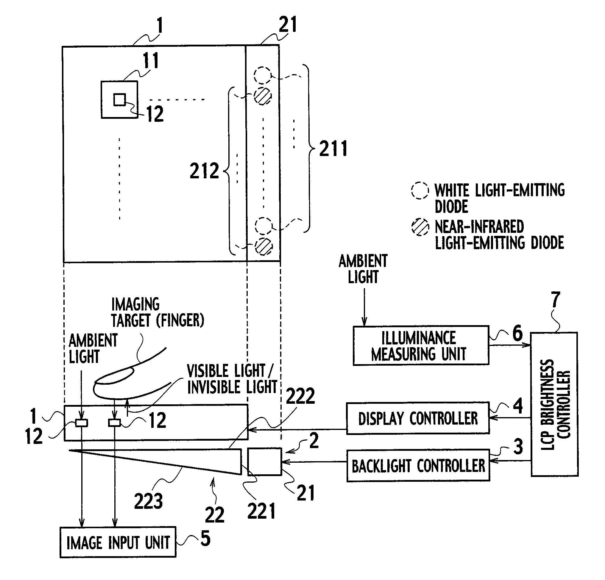
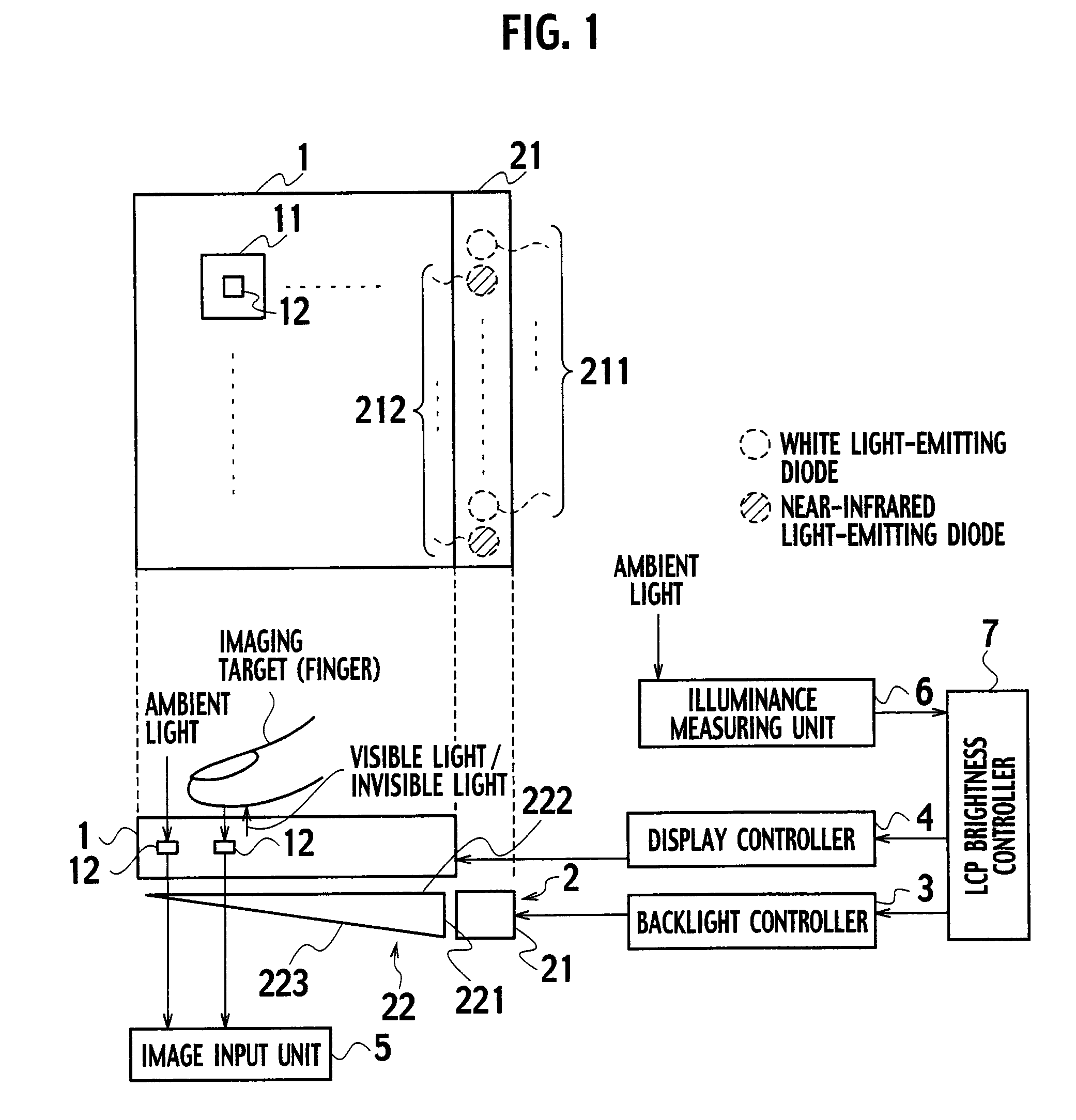
[0030]As shown in FIG. 1, a liquid crystal display device according to an embodiment(hereinafter referred to as the device) has a liquid crystal panel 1, a backlight 2, a backlight controller 3, a display controller 4, an imaging unit 5, an illuminance measuring unit 6, and a liquid crystal panel brightness controller (hereinafter referred to as an LCP brightness controller) 7.

[0031]For displaying an image, display elements 11 are two-dimensionally arranged in the liquid crystal panel 1.

[0032]In the liquid crystal panel 1, photosensors 12 are also arranged. For example, each one or three display elements 11 have the photosensor 12.

[0033]Specifically, the liquid crystal panel 1 has a liquid crystal layer, an array substrate and an opposite substrate, all not shown in the figures. The liquid crystal layer is disposed between the two substrates.

[0034]In the array substrate, a plurality of signal lines and a plurality of scanning lines are disposed to cross each other. The display eleme...


PUM


Abstract

A liquid crystal panel brightness controller notifies a backlight controller that an illuminance of ambient light is equal to or less than a threshold value. Upon notification, the backlight controller causes invisible light emitted, for example. The invisible light passes through a liquid crystal panel and is reflected by an imaging target and is received by photosensors. Accordingly, the decrease in the amount of the visible light received by photosensors is compensated. As a result, an image with a high S / N ratio is obtained.

Description

CROSS-REFERENCE TO RELATED APPLICATIONS[0001]This application is based upon and claims the benefit of priority from Japanese Patent Application No. 2006-172562 filed Jun. 22, 2006; the entire contents of which are incorporated herein by reference.BACKGROUND OF THE INVENTION[0002]1. Field of the Invention[0003]The present invention relates to a liquid crystal display device achieving imaging with a high S / N ratio using an invisible light source in addition to a visible light source.[0004]2. Description of the Related Art[0005]A liquid crystal display device has an array substrate in which signal lines, scanning lines, thin film transistors (TFT) and the like are formed. The device also has a driving circuit for driving the signal lines and the scanning lines.[0006]Recently, as the technology in integrated circuit has been developed, TFTs and a driving circuit can be formed in an array substrate by polysilicon process.[0007]This makes a liquid crystal device be miniaturized. And the d...

Claims


Application Information

Patent Timeline
Patent Type & Authority Applications(United States)
IPC IPC(8): G09G3/36
CPCG02F1/13318G02F1/13338G02F2001/13312G06F3/042G06F3/0412H04N5/23293H04N5/2354G02F2203/11G02F1/13312H04N23/74
Inventor NAKAMURA, HIROKINAKAMURA, TAKASHIHAYASHI, HIROTAKATADA, NORIOIMAI, TAKAYUKI
Owner JAPAN DISPLAY CENTRAL CO LTD
Why Eureka
Try Eureka