Imaging apparatus

a technology of imaging apparatus and image, which is applied in the field of imaging apparatus, can solve the problems of long initializing time, large demand for a recording medium having a large memory capacity, and long time, and achieve the effects of shortening the time, shortening the time, and fast initializing tim

Active Publication Date: 2007-12-27
MAXELL HLDG LTD
View PDF5 Cites 148 Cited by
  • Summary
  • Abstract
  • Description
  • Claims
  • Application Information

AI Technical Summary

Benefits of technology

[0010]With a video camera or a digital camera, for reducing electric power consumption for driving by means of a battery, an electric power of the recording means is in the condition of OFF, when it is in the power OFF condition thereof, and therefore, for a user it results into loosing a change to take a picture of an important scene, if the waiting time is long from when operating the electric power ON up to when it enables photographing and recording. For that reason, it is preferable to shorten a waiting time from the time when it is operated with the electric power ON up to when it comes to be recordable.
[0012]Also, with the initializing process shown in the Patent Document 2, assuming that, in case where there are units having the same function thereof, in a plural number thereof, in many cases, the user utilizes them for the purpose of “using which function thereof”, but rather “using which unit thereof”, therefore the initializing process is executed from the unit, which has a fast initializing time, while using it when that unit comes to be usable, the initializing process is executed on the unit, which has a late initializing time next to the fast one, and thereby achieving the shortening of the time until when the user comes to be utilize the function mentioned above. Explaining by taking an imaging apparatus, for example, it corresponds to an imaging apparatus achieving a function of recording of a moving picture by means of two (2) pieces of units, such as, the magnetic tape and the memory card, for example. Since the user selects the function of recording a moving picture, then recording is made into the memory card having the short initializing time, between the magnetic tape and the memory card, first, and then is made onto the magnetic tape after completing the initializing process of the tape recorder, and thereby reducing or shortening the time until the time when the moving picture can be recorded. However, in case of two (2) recording apparatuses, such as, a hard disk and an optical disk, for example, where a long time recording of the moving picture can be made can on either one of them, it is preferable that the recording is made only on the recording means having a shorter initializing time, however with the conventional technology of this Patent Document 1, there is a problem that the data to be recorded is divided, to be recorded onto the memory card and the magnetic tape, separately.
[0013]Also, the camera is the thing to be carried by, i.e., being portable; therefore, it is required to be small in the sizes thereof. Then, with buttons or the like, to be used for conducting the operations while mounting a plural number of recording media thereon, it is impossible to arrange them by the number being same to that of the functions thereof; therefore, a technology is required for operating such the camera, mounting the plural number of recording media thereon and being multi-functional, with practically using the restricted number of buttons, effectively.

Problems solved by technology

With the increase of the pixel number, for this reason, demanding is large for a recording medium having a large memory capacity.
For a magnetic tape recorder, taking a long time for loading operation of a mechanism therein, it takes the initializing time longer than that of the memory card.
However, with the switch disclosed in the Patent Document 1, no consideration is made upon recording a moving picture into a plural number of recording media.

Method used


Image

  • Imaging apparatus
  • Imaging apparatus
  • Imaging apparatus

Examples


embodiment 1

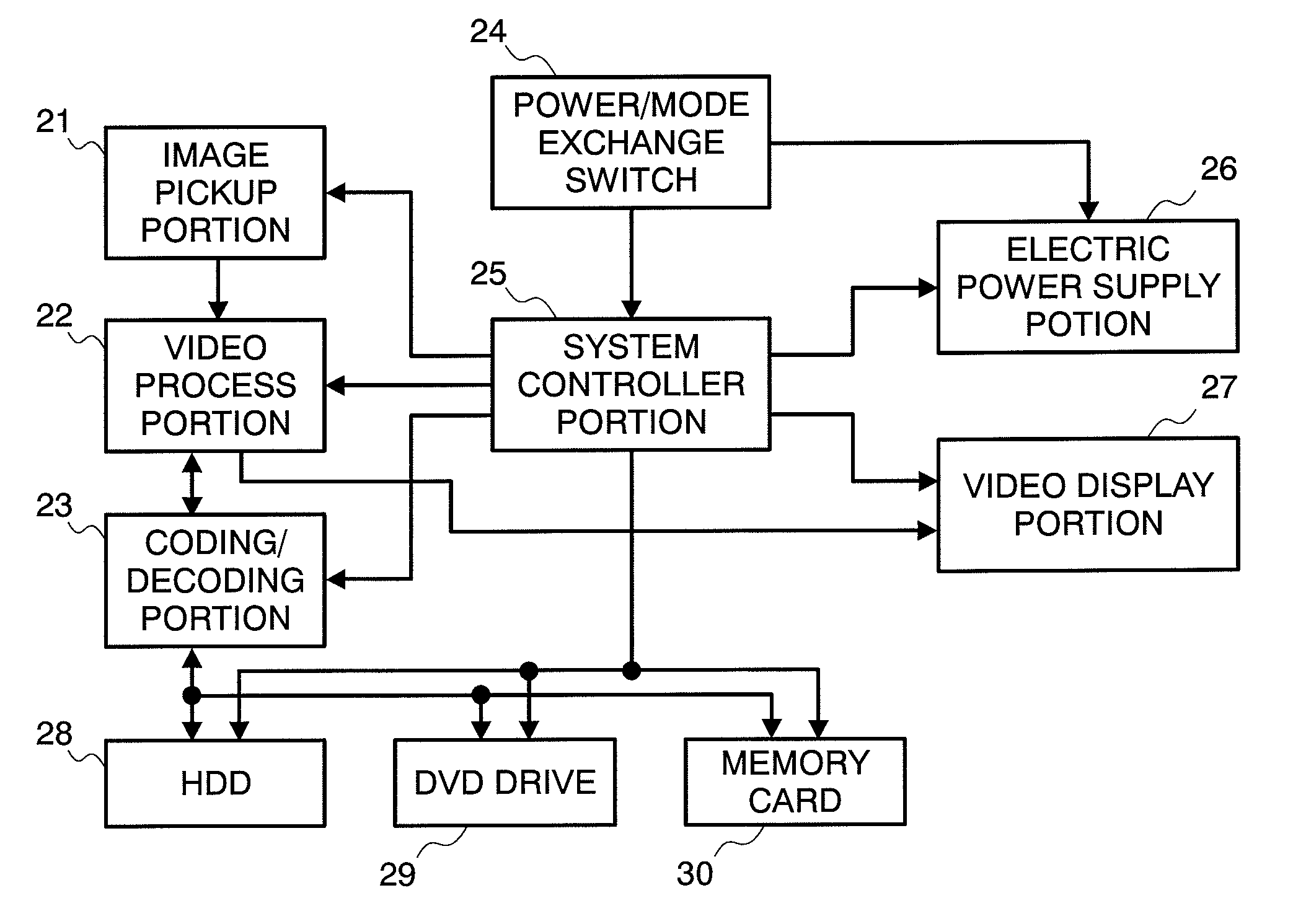
[0029](1) Structures of Video Camera

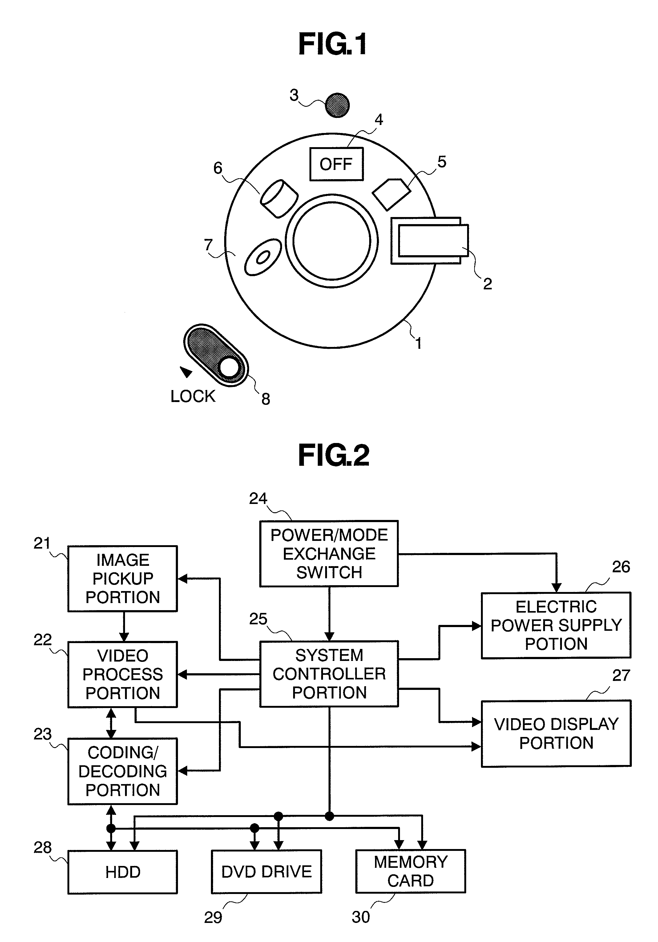
[0030]FIGS. 4(a) and 4(b) and 8 show an example of outlook of a digital video camera, i.e., being a photographing apparatus. FIG. 4(a) shows a rear perspective view of the video camera, and FIG. 4(b) a rear front view thereof.

[0031]On a rear portion (i.e., on a side of a photographer) is arranged a power / mode exchange switch 24 for use of turning ON / OFF of an electric power and exchange the mode thereof. Thus, it is located at such a position that the switch can be operated with a thumb when a user holds the video camera on her / his hand, with passing a hand through a belt 31. Also, a lock switch 8 is provided on a rear portion, to be operable with the thumb, in the similar manner. A shutter button 32 for photographing a still picture, a power-save button 33 for turning the camera into a power saving condition differing from a turning-OFF of an electric power and also for releasing from that power saving condition, and a zoom button 34 for indicati...

embodiment 2

[0070]Explanation will be made on an embodiment 2, wherein it differs from the embodiment 1 in a shape of the power / mode exchange switch 24.

[0071]FIG. 5 is an outlook view for showing an example of the shape of a power / mode exchange switch 24 according to the second embodiment. Differing from that shown in FIG. 1, a reference mark 103 indicating the position of the switch is printed on a dial portion 101, when the user rotates the dial portion while holding a projection portion 102, the reference mark mentioned above also rotates accompanying with that. Also, NO / OFF of the electric power can be selected by rotating the dial portion 101, so as to move the above-mentioned reference mark 103 to a portion of an IN-mode select display 109 or an OUT-mode select display 104. However, for switching over the HDD mode, the DVD mode and the memory card mode, switching is made, sequentially, while pushing the dial portion 101 from the IN-mode select display, further down to the position of “Mod...

embodiment 3

[0076]Explanation will be made on an embodiment 3, wherein it differs from the embodiment 1 in timing of starting the initialization of the DVD.

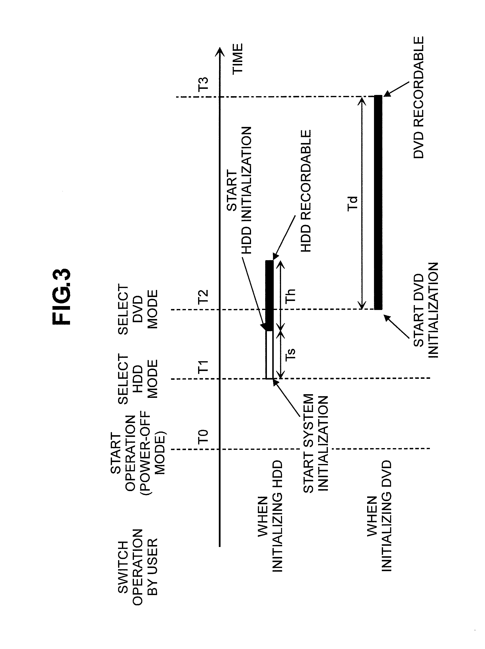
[0077]FIG. 7 is a timing view for explaining about the initialization time in the embodiment 3.

[0078]When initializing the DVD, the system of the present video camera starts the initialization at the time when the power / mode exchange switch 24 is shifted from the position of power OFF to the position for selecting the HDD mode, and further after elapsing the time (T1+Ts), initialization is started on the HDD 28 and the DVD drive 29. Thereafter, after elapsing the time (T1+Ts+Td) adding the initialization time of the DVD drive 29 thereto, the DVD drive 29 comes to be recordable. On the other hand, the user turns the power / mode exchange switch 24 further, for turning the it to the DVD position, and after the time (T2), the camera comes into the DVD mode.

[0079]In this manner, since the initialization of the DVD drive 29 is started prior to the ...


PUM


Abstract

An imaging apparatus, comprising: a first recording module, which has a first initialization time from initialization to coming into a recordable condition; a second recording module which has a second initialization time from initialization to coming into a recordable condition, being longer than the first initialization time; a mode switching module, which is configure to switch over a power OFF mode, a mode for recording into the first recording module, and a mode for recording into the second recording module, wherein the mode exchange switch, which is configured to exchange the mode in an order from the power OFF mode to the mode for recording into the first recording module, and to the mode for recording into the second recording module, whereby shortening an apparent initializations time of the recording module having a long initialization time, while using a high-speed initialization characteristic of the recording module having a short initialization time effectively, thereby obtaining an improvement on the operability for a user.

Description

BACKGROUND OF THE INVENTION[0001]The present invention relates to an imaging apparatus, and in particular, it relates to an operating portion of the imaging apparatus.[0002]In relation to a switch for starting or initializing a came, as being an operating portion of the imaging apparatus, for example, in Japanese Patent Laying-Open No. Hei 6-6651 (1994), there is the following description:[0003]“While being provided with a video tape-recorder mode side silk-screen printing 3 and a camera mode side silk-screen printing 5, on a side surface in the thickness direction of a rotating ring-like operation key 1, an electric power switch mark 7 at the position opposite to the silk-screen printing 3 and 5, a reproduction mark 9 for indicating a reproducing portion on a side surface in the thickness direction of the operation key 1, an edit mark for indicating a position switching into an editing function, and a line input / output mark 13 for indicating a position of switching between line inp...

Claims


Application Information

Patent Timeline
Patent Type & Authority Applications(United States)
IPC IPC(8): H04N5/76
CPCH04N5/232H04N5/23245H04N5/772H04N21/42661H04N5/907H04N9/8042H04N21/42646H04N5/84H04N23/531H04N23/60H04N23/667
Inventor OTA, MASATAKAFUJIMOTO, MASAHIRO
Owner MAXELL HLDG LTD
Why Eureka
Try Eureka