Optical Integrator, Illuminator and Projection Type Image Display

a technology of optical integrator and illuminator, which is applied in the direction of projectors, color television details, instruments, etc., can solve the problems of increasing the size and weight of the unit, increasing the cost of the unit, and increasing the efficiency of the light source when used, so as to reduce the number of parts, shorten the length of the light path, and reduce the effect of the number of parts

Inactive Publication Date: 2007-12-27
SHARP KK
View PDF7 Cites 32 Cited by
  • Summary
  • Abstract
  • Description
  • Claims
  • Application Information

AI Technical Summary

Benefits of technology

[0063] According to the present invention, an optical integrator is integrally formed by providing an optical film for selectively reflecting and transmitting light for each wavelength band on the joined surfaces which are inclined between the number of block materials, and therefore, the efficiency of the light source when used can be increased, and the configuration for changing the light path and making illumination uniform can be greatly simplified in comparison with the prior art, reduction in the number of parts and shortening of the length of the light path can be achieved, and at the same time, reduction in the size and cost of the illuminator and the projection type image display can be achieved.
[0064] In addition, according to the present invention, an optical integrator having reflection properties on the created inclining surfaces is used, and therefore, the configuration for changing the light path and making illumination uniform can be simplified using only an optical integrator having a more simple configuration, which further contributes to reduction in the size and cost of the illuminator and the projection image display.
[0065] Furthermore, according to

Problems solved by technology

First, the wavelength range of light emitted from the lamp includes ultraviolet rays and infrared rays, and therefore, a problem arises, such that the light bulb (DMD or liquid crystal panel) and other parts are subjected to the effects of heat.
In addition, it becomes necessary to provide a cooling fan inside the unit, in order to avoid the effects of heat, or an ultraviolet ray and infrared ray cutting filter in the emission portion of the lamp, and thus, the cost of the unit increases and a big noise is generated by the fan during operation of the unit, and furthermore, this leads to increase in the size and weight of the unit.
Moreover, in the case of a lamp type, the image displayed on the screen becomes dark when the life of the lamp expires, after lighting of 2,000 hours to 4,000 hours, and thus, the lamp must be replaced, which is expensive

Method used


Image

  • Optical Integrator, Illuminator and Projection Type Image Display
  • Optical Integrator, Illuminator and Projection Type Image Display
  • Optical Integrator, Illuminator and Projection Type Image Display

Examples


first embodiment

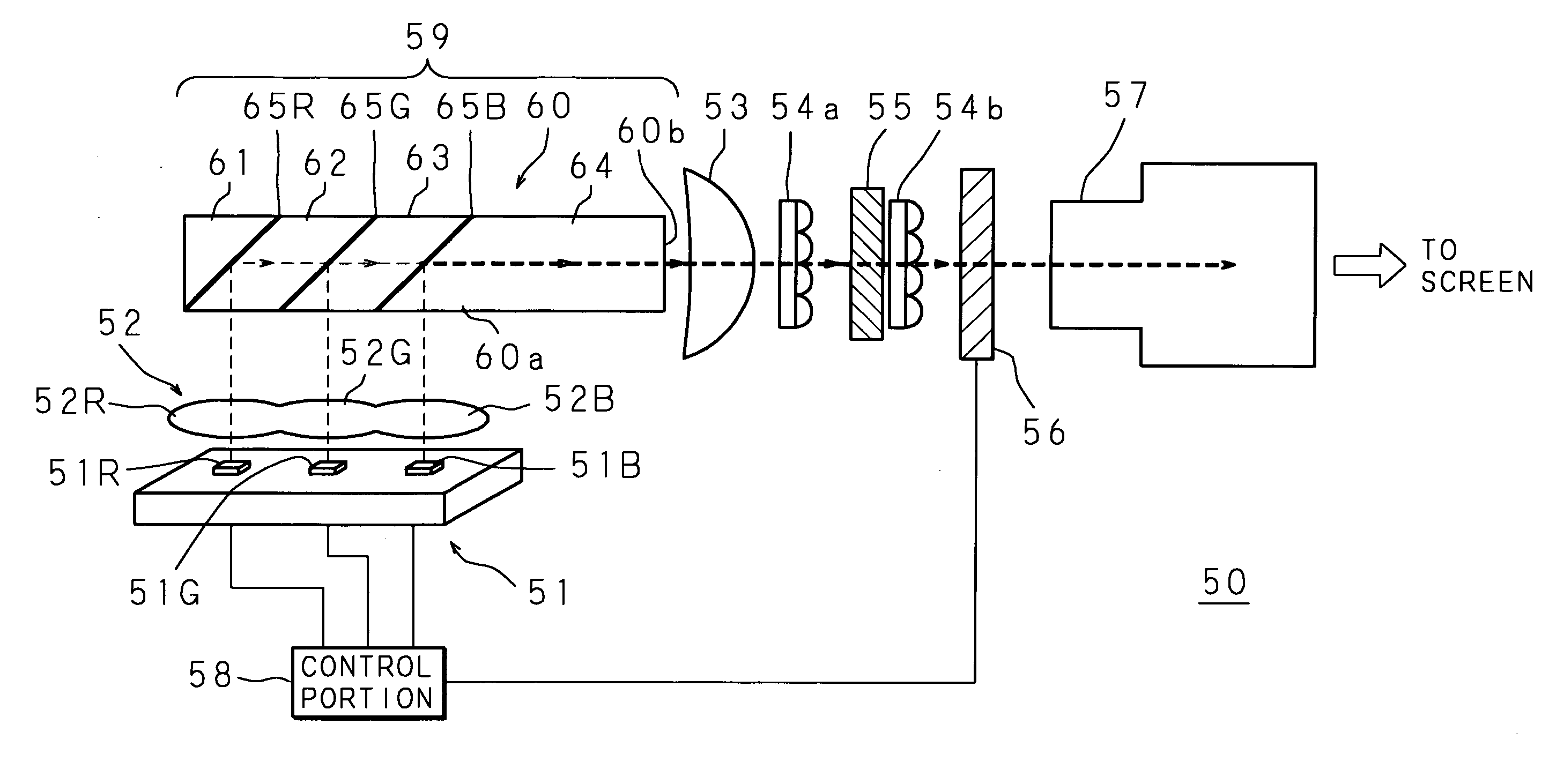
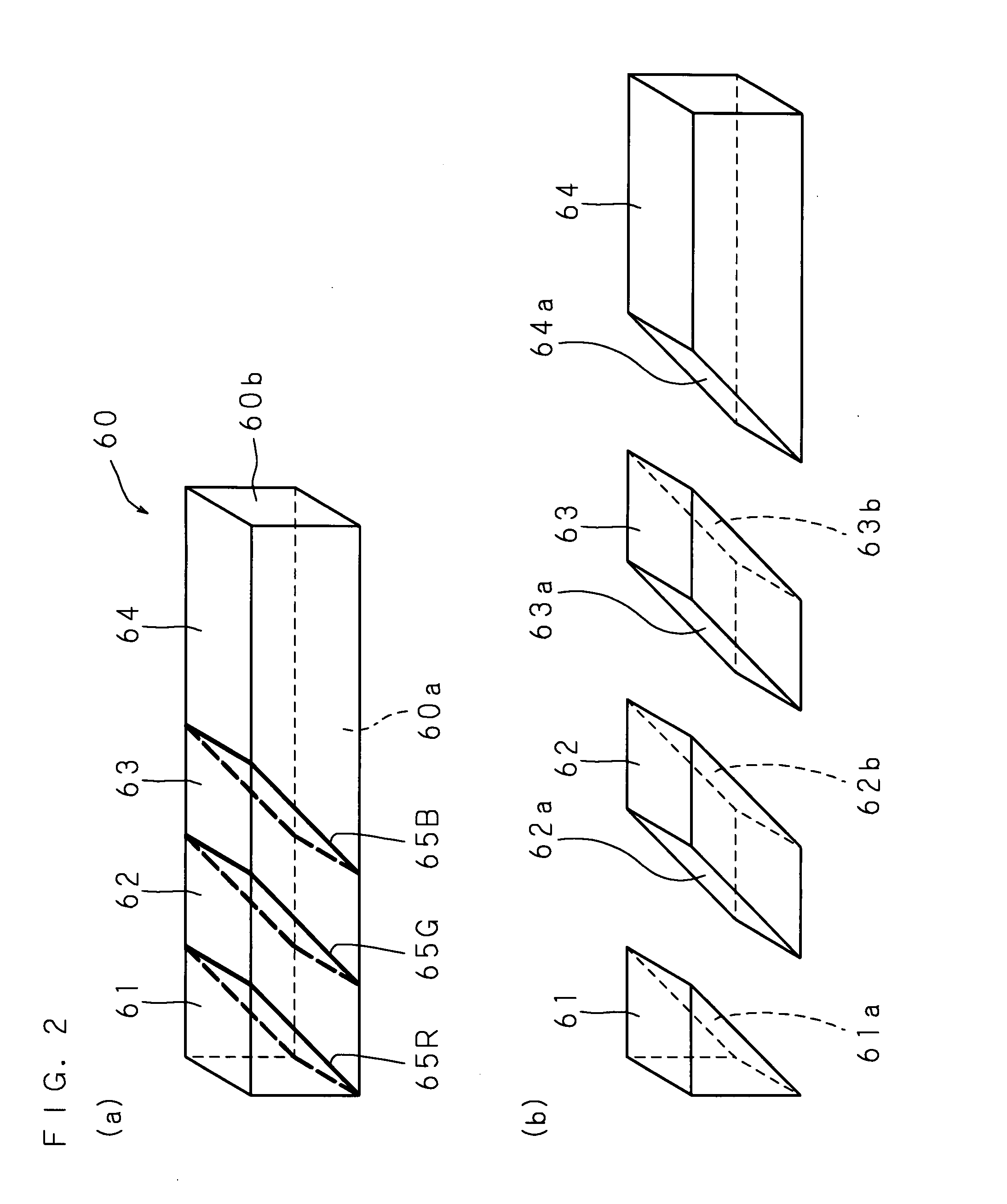
[0107]FIG. 1 shows the configuration of a projection type image display 50 (including an illuminator 59) according to the present invention, and the projection type display 50 according to the present embodiment is formed so as to comprehensively include a great number of components according to the present invention, and has a form which is appropriate for reducing the cost and size.

[0108] The projection type image display 50 uses a red LED 51R, a green LED 51G and a blue LED 51B, which are a number of light emitting elements, as the light source, and a first lens 52 is placed so as to face the LED's 51R, 51G and 51B, and at the same time, an optical integrator 60 in columnar form is placed so that emitted light which passes through this first lens 52 enters the optical integrator 60. Furthermore, in the projection type image display 50, a second lens 53, a first fly eye lens 54a, a PS separation and synthesis unit 55, a second fly eye lens 54b, a transmission type liquid crystal p...

second embodiment

[0151] In addition, in the optical integrator 80 the reflective film 85 can be formed of a multilayer film or a hologram functional element or a mirror can be used instead of the reflective film 85. Furthermore, it is also possible to place a PS separation and synthesis unit 55 on the upstream side from the entrance surface 80a of the optical integrator 80. In this case, light emitted from the light source is polarized on one side by the PS separation and synthesis unit 55, before being emitted to the optical integrator 80, and thus, light emitted from the light source can be totally reflected and emitted through the emission surface 80b using the difference in the index of refraction between the respective block materials 82, which are a glass base, and the surrounding air, without providing a reflective film 85, a hologram functional element or a mirror on the joined surface 81a of the first block material 81 or the joined surface 82a of the second block material 82 in the optica...

third embodiment

[0156] In the projection type image display 90 G light beams emitted from the number of green LED's 91G pass through the lens for green 92a and enter through the first entrance surface 100a of the optical integrator 100 so as to illuminate the dichroic mirror 105G, and then reflected from the dichroic mirror 105G and repeatedly totally reflected, and propagate through the optical integrator 100 and are emitted from the emission surface 100b with uniform illumination. In addition, R and B light beams emitted from the two red LED's 91R and the blue LED 91B, respectively, pass through the lens for red and blue 92b, enter through the second entrance surface 100d of the optical integrator 100 so as to illuminate the dichroic mirror 105G, and then transmit through the dichroic mirror 105G, are repeatedly totally reflected, and propagate through the optical integrator 100 so as to be emitted from the emission surface 100b with uniform illumination.

[0157] Thus, in the projection type image...


PUM


Abstract

In a projection type image display 50, LED's 51R, 51G and 51B are used as the light source so that the emitted light beam enters into an optical integrator 60. The optical integrator 60 is formed of four block materials 61 to 64 which are joined in the longitudinal direction, and a dichroic mirror 65R which reflects R light beams and transmits G and B light beams, a dichroic mirror 65G which reflects G light beams and transmits R and B light beams, and a dichroic mirror 65B which reflects B light beams and transmits R and G light beams are provided so as to be integrated with the joined surfaces which are inclined between the respective block materials 61 to 64.

Description

TECHNICAL FIELD [0001] The present invention relates to an optical integrator and an illuminator which makes highly efficient use of a light source, as well as a projection type image display of which the size can be reduced and which implements high quality image display. BACKGROUND TECHNOLOGY [0002] There are conventional front projection type projectors (projection type image displays) for displaying images on a screen which project modulated light for images generated by a light source onto a screen. In addition, the configuration of such projection type image displays is applied to rear projection type displays, such as rear projection TV's. Projection type image displays include those using a lamp as the light source, as well as those using light emitting elements, such as lasers or diodes. Meanwhile, if categorized by the type of spatial light modulator (light bulb) for generating original images which are an object to be projected, they can be divided into those using a DMD ...

Claims


Application Information

Patent Timeline
IPC IPC(8): G02B27/10
CPCG02B27/1053G02B27/145G02B27/149H04N9/3197H04N9/3111H04N9/3152G03B21/14G03B21/2066G03B33/12G03B21/00G02B27/00
Inventor KYOMOTO, TADAOIWAUCHI, KENICHI
Owner SHARP KK
Why Eureka
Try Eureka