
Self powered supply for power converter switch driver

a switch driver and self-powered technology, applied in power conversion systems, electrical equipment, electrical apparatus, etc., can solve the problems of occupying valuable space by the driver power source and isolation transformer, and adding significant cost to so as to reduce the cost and size of the power conversion system, and save space and cost.

Active Publication Date: 2007-12-27
ROCKWELL AUTOMATION TECH
View PDF12 Cites 41 Cited by
  • Summary
  • Abstract
  • Description
  • Claims
  • Application Information

AI Technical Summary

Benefits of technology

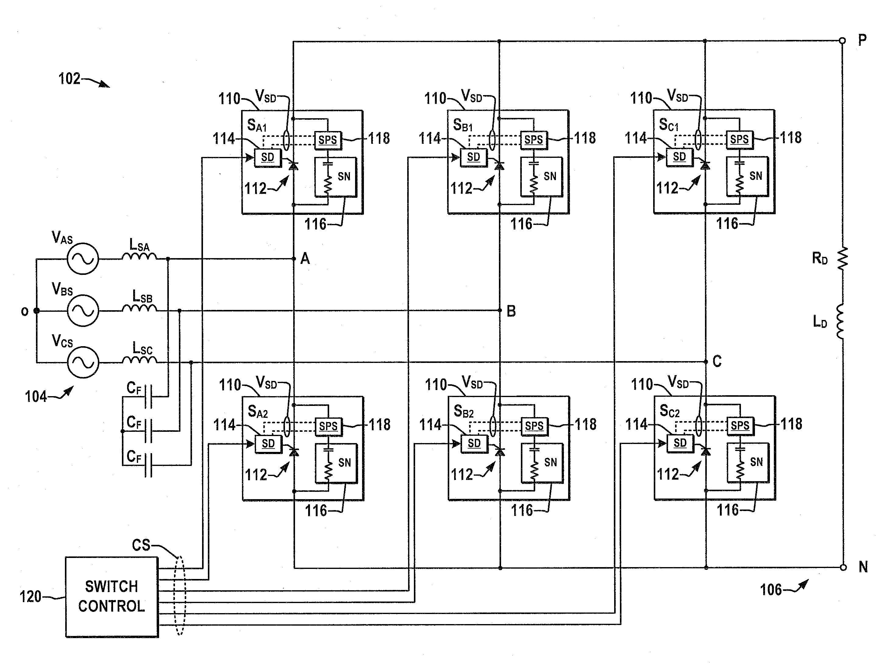
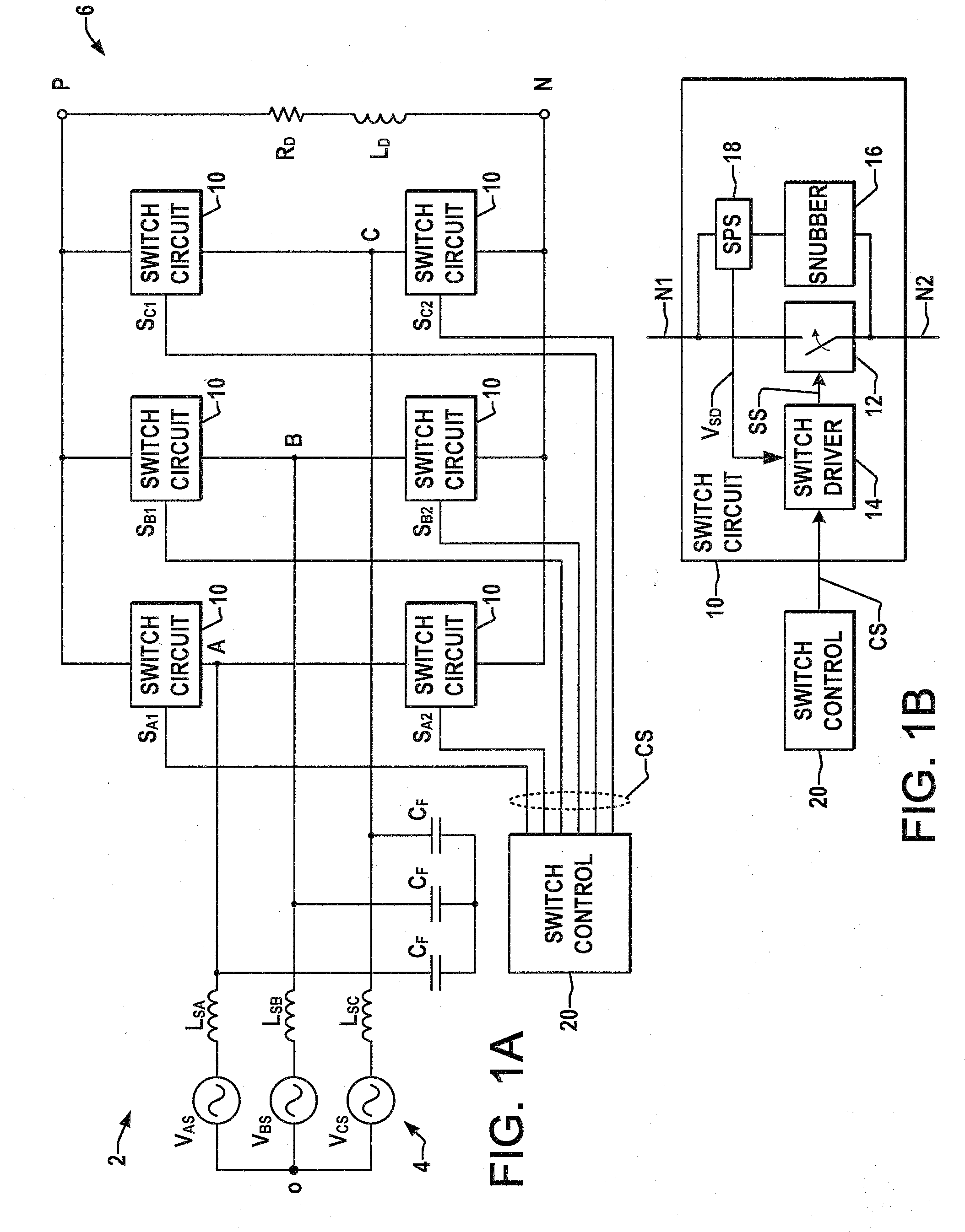
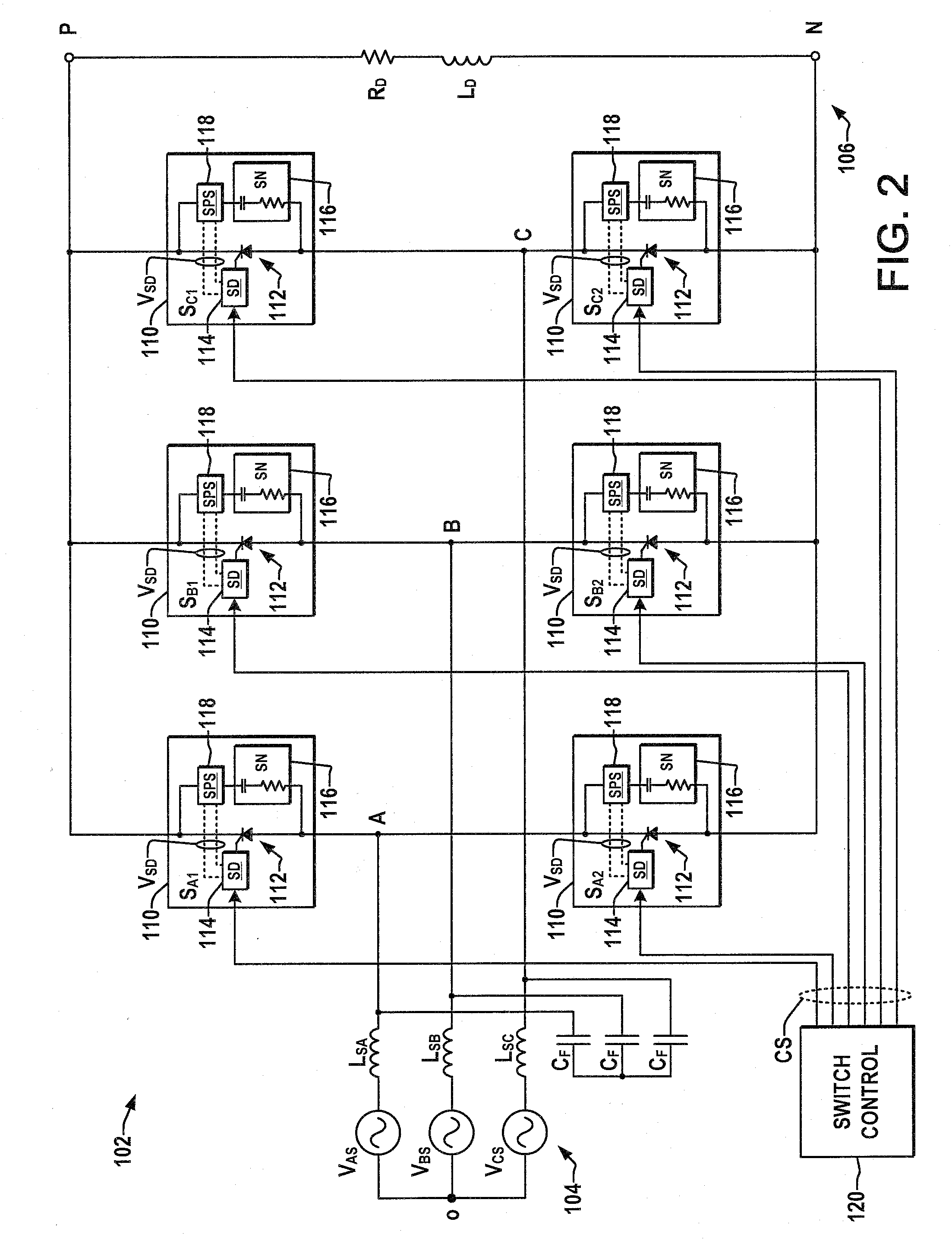
[0003]Various aspects of the present invention are now summarized to facilitate a basic understanding of the invention, wherein this summary is not an extensive overview of the invention, and is intended neither to identify certain elements of the invention, nor to delineate the scope thereof. Rather, the primary purpose of this summary is to present some concepts of the invention in a simplified form prior to the more detailed description that is presented hereinafter. The goal of reducing the cost and size of power conversion systems is addressed through the provision of a self-powered supply (SPS) that obtains energy from the snubber circuit associated with a power switching device and generates an isolated dc voltage for the gate driver. The SPS and the snubber form a series circuit between the switch device terminals such that the snubber circuit will transfer charging currents to a storage device in the SPS from which the switch driver power is derived. In this manner, the driver power is obtained from the energy accumulated by the snubber and is isolated with respect to the system ground and the snubber voltage, thereby saving space and cost in the construction of power conversion systems such as motor drives, etc.

Problems solved by technology

However, these driver power sources and isolation transformers occupy valuable space and add significant cost in power conversion systems, particularly for medium or high voltage systems operated with GCT or IGCT type switches.

Method used


Image

  • Self powered supply for power converter switch driver
  • Self powered supply for power converter switch driver
  • Self powered supply for power converter switch driver

Examples


Embodiment Construction

[0012]Referring now to the figures, several embodiments or implementations of the present invention are hereinafter described in conjunction with the drawings, wherein like reference numerals are used to refer to like elements throughout, and wherein the various features are not necessarily drawn to scale.

[0013]Referring initially to FIGS. 1A and 1B, FIG. 1A illustrates an exemplary power conversion system or power converter 2 having a plurality of self-supplied switch circuits 10 for controlled conversion of input electrical power to output electrical power in accordance with various aspects of the present invention. The exemplary power converters 2 and 102 illustrated herein are pulse width modulated (PWM) current source rectifiers (CSRs) finding utility in high-power drives for electric motors, and the various features of the present invention are illustrated and described hereinafter in this context. However, it will be appreciated that the invention may be advantageously employ...


PUM


Abstract

Self-powered supplies are presented for powering a power converter switch driver with power obtained from an associated snubber circuit, in which a supply circuit and a snubber circuit are connected in a series path across the switch terminals with the supply circuit receiving electrical power from the snubber and providing power to the switch driver.

Description

FIELD OF THE INVENTION[0001]The present invention relates generally to electrical power conversion and more particularly to self-powered switch driver systems for power converters.BACKGROUND OF THE INVENTION[0002]Power conversion systems are employed to convert electrical power from one form and / or level, whether AC or DC, to another (AC or DC) in a multitude of applications. One example is a pulse width modulated (PWM) current source rectifier used in high-power motor drives with AC input power being selectively switched to create a DC output bus voltage from which a load is driven. Power converters may include multiple stages for different types of conversion applications, such as AC / DC / AC drives for electric motors, in which input AC power of a given frequency and voltage is first converted to a DC bus, with a second stage selectively switching the DC bus power to create single or multi-phase AC output power of variable voltage and / or frequency. This type of converter is particul...

Claims


Application Information

Patent Timeline
Patent Type & Authority Applications(United States)
IPC IPC(8): H02H7/10
CPCH02M1/08H02M7/162H02M1/32
Inventor ZARGARI, NAVID REZAWU, BINHU, WEIQIAN
Owner ROCKWELL AUTOMATION TECH
Learn More