Camera systems, methods and units therefor

a technology of camera system and camera body, applied in the field of remote camera system, can solve the problems of defective unit or unit being taken out of service for repair, virtual waste of products, and down time, and achieve the effects of convenient replacement, convenient connection and removal, and sufficient cos

Inactive Publication Date: 2007-12-27
LANGE FREDERICK M
View PDF7 Cites 32 Cited by
  • Summary
  • Abstract
  • Description
  • Claims
  • Application Information

AI Technical Summary

Benefits of technology

[0007] The system and units thereof embodying the invention include a conduit inspection video camera, a cable push rod, the electronic controls for the camera, and a carrier for the cable push rod and the electronic controls. The camera and the electronic controls are such that they are compatible with any video equipment or recorder that has an input video jack. The camera is quickly and easily connected to and removed from an end of the control push rod, since the control push rod or cable also contains the necessary wiring and connections to connect with the camera at one end and to connect with the electronic controls for the camera at the opposite end. These connections are all the plug-in type, which have not been successfully accomplished and marketed before this invention. The cable and control push rod assembly has plugs on each end so that the camera may have one end of the cable plugged into it, and the electronic controls may also have the other end of the cable plugged into it. A sturdy rotary contact assembly provides the requisite connection from the control panel to the cable push rod assembly that is on the rotatable reel of a carrier. The control box assembly contains the control panel and the control system. The control box assembly and the cable push rod are also supported by the carrier. Even when the cable push rod assembly is fully unreeled for use, one end of it is still operatively connected to the control box assembly through a rotary contact assembly. The other end is connected to the camera assembly. The electronic controls have an output cable which can be connected to any video equipment having a standard video input. This includes video recorders, DVD recorders, VHS recorders, even ipods and MP3s, as well as various video viewing screens such as television screens and computer screens. All of this, other than the video equipment, is compactly supported by a carrier that includes the reel for holding the cable (which is also called the control, the cable push rod, or the push rod assembly). The video equipment, or a combination of more than one piece of such equipment, may be located a short distance away from the carrier and the system parts that are supported on the carrier. They can even be also located at other sites such as an office, with the signals to them being transmitted in any of several manners. While the system shows the video equipment connected to the control box assembly by wiring, it is to be understood that this may alternatively be a wireless connection such as is now well known and is in common use in many computer installations. Since the electronic controls are no longer in the video equipment, any video equipment having a standard video input receptacle may be used. With the advent of the inventive system and units of that system as disclosed herein, each of these units can be replaced by the customer that is using the system, making the ability to return the system quickly into operation. The customer / user only has to either stock some spare units or to have them available to him within hours, commonly overnight, instead of days. Spare video equipment is now sufficiently inexpensive to easily have some spares when needed. They have virtually become throwaway products because of their low purchase costs. That cannot be said of the combined controls and monitors in other systems. Then, the defective unit or units may be taken out of service for repair if that is absolutely necessary, but not without causing any down time and all the other costly consequences of that. Experience has already shown that even a camera lens, for example, can be easily replaced by someone with no particular skills. This is never even an option with the other currently produced systems. Different ones of the systems that have been available for some years have so customized their combined monitors and controls that at many times no one system can even use such parts of another system. This also adds to costs for the user that were and still are unavoidable with those systems.

Problems solved by technology

They have virtually become throwaway products because of their low purchase costs.
Then, the defective unit or units may be taken out of service for repair if that is absolutely necessary, but not without causing any down time and all the other costly consequences of that.
This is never even an option with the other currently produced systems.
This also adds to costs for the user that were and still are unavoidable with those systems.

Method used


Image

  • Camera systems, methods and units therefor
  • Camera systems, methods and units therefor
  • Camera systems, methods and units therefor

Examples


Embodiment Construction

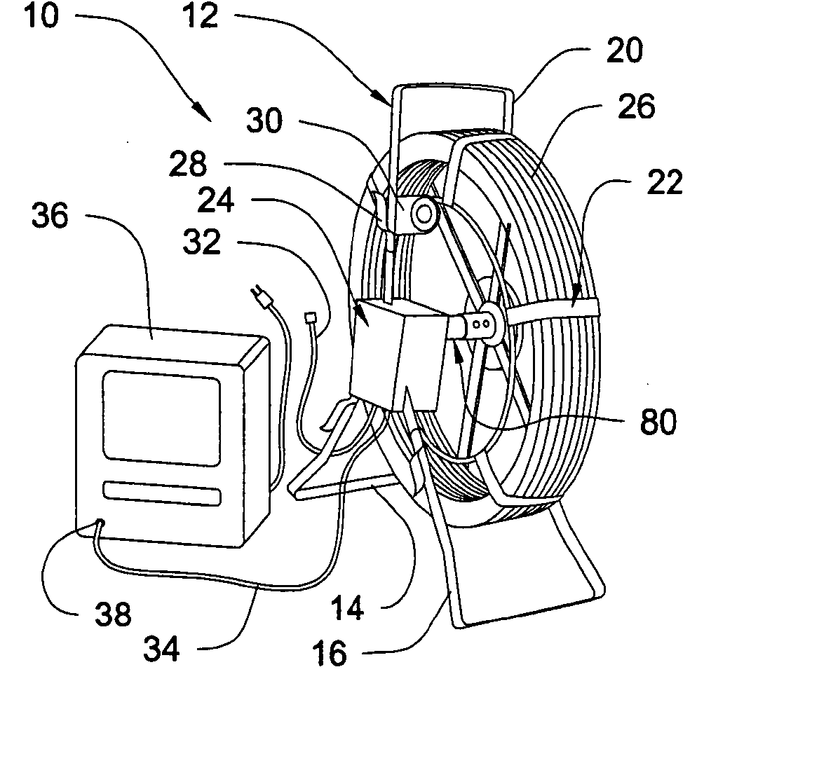
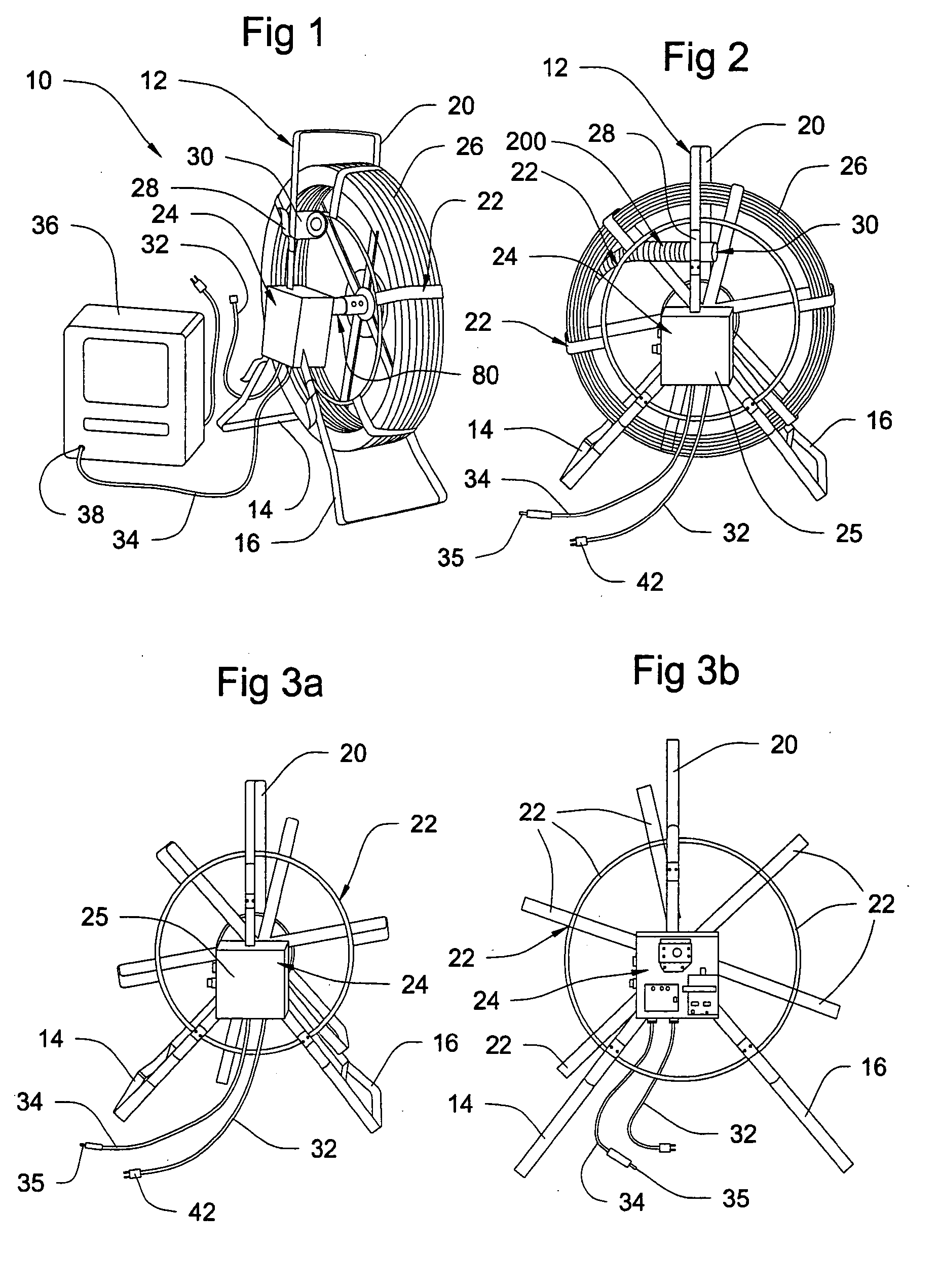
[0021] The system 10 embodying the invention is shown in FIG. 1 as including a carrier 12 having support legs 14 and 16 supporting a stationary hub 18, a carrying handle 20, a reel 22 which is rotatable on hub 18, a control box assembly 24, a push rod assembly 26 wound on the reel 22, a receptacle 28 for holding a small video camera assembly 30 when the system is not in use and has the push rod assembly 26 coiled up on the reel 22, a power cord 32 and a video cable 34 having a standard video input plug 38 on its end. The system also has video equipment 36 which may include a video recorder or some other type of video equipment. The video cable 34 is connected by its standard input plug 35 to the standard video signal input connection 38 of the video equipment 36, as well as being operatively connected to the camera assembly 30 through the control box assembly 24 and a rotary contact assembly connector 80, better seen in FIGS. 7A, 7B, 7C and 7D, and the push rod assembly 26. FIG. 2 a...


PUM


Abstract

A system whose most common use is that of inspecting conduits such as sewers, drainage pipes, water, gas and oil conduits. Contrary to camera systems currently on the market, the system has individual components that are easily disconnected and reconnected so that a failed component can be determined and replaced in the field, yet it maintains its integrity against damage from the type of effluent in which it is required to operate. The system's control unit is easily disconnected and replaced, and is mounted on a carrier. The system includes a push rod assembly that has male or female plugs providing quick disconnects at each end so that it can readily be disconnected from opposite gender plugs on a rotary contact assembly at one end and a video camera assembly at its other end. The rotary contact assembly is mounted on the carrier and is similarly connected to and from the control unit, which is physically separate and is also mounted on the carrier. The carrier also has a reel on which the push rod assembly is stored. Electrical power is provided from a power source for the camera and the video equipment that receives video signals from the camera. The power source may or may not be mounted upon the carrier. The novel splices between the wires of various units and either a male or a female plug by which units are connected are a major contribution to the success of the invention. Similar splices can also be used for field repairs to damaged push rod assemblies or for increasing the overall length of the push rod assembly.

Description

[0001] Priority is claimed based on the U.S. Provisional Application Ser. No. 60 / 815,366, inventor Frederick M. Lange, Attorney File No. LJ-305, having the title of “Camera System and Units Thereof” and filed in the United States Patent and Trademark Office on Jun. 21, 2006. That application is hereby incorporated herein by reference.BACKGROUND OF THE INVENTION [0002] Cameras are currently being used in a unitary manner with a video receiver, a cable connecting a video receiver and the camera, and a control system for controlling the camera. Such systems are often used by plumbers and other related occupations for inspecting a conduit and often for finding the exact location and nature of a fault in a conduit or pipe system, whether it be a supply of water, fuel or waste matter. At the time of making this invention there were no camera systems on the market that did not require return to the manufacturer or a special repair station for even the simplest repair or replacement. This i...

Claims


Application Information

Patent Timeline
Patent Type & Authority Applications(United States)
IPC IPC(8): G03B37/00
CPCG03B37/005
Inventor LANGE, FREDERICK M.
Owner LANGE FREDERICK M
Why Eureka
Try Eureka