
Medical System

a technology of a medical system and a rotational processing device, applied in the field of medical systems, can solve problems such as the perspective of high-precision rotation correction, and achieve the effect of high-precision rotation processing

Active Publication Date: 2007-12-27
OLYMPUS CORP
View PDF12 Cites 62 Cited by
  • Summary
  • Abstract
  • Description
  • Claims
  • Application Information

AI Technical Summary

Benefits of technology

[0010] With the aforementioned arrangement, the information regarding the rotating angle of the rotating device of medical device is acquired at the image capturing timing performed by the image pickup device provided to the rotating medical device. This allows acquisition of the information regarding the rotating angle with respect to the actual image capturing timing performed by the image pickup device. Rotation correction is performed based upon the rotating-angle information, thereby enabling high-precision rotation processing.

Problems solved by technology

However, the aforementioned prior art has a configuration in which the image data is stored by the image processing device outside of the body in a form correlated with the information regarding the rotational magnetic field at the time of the image data acquisition, thereby leaving a problem from the perspective of higher-precision rotation correction.

Method used


Image

  • Medical System
  • Medical System
  • Medical System

Examples


embodiment 1

[0085] Description will be made regarding an embodiment 1 with reference to FIGS. 1 through 9.

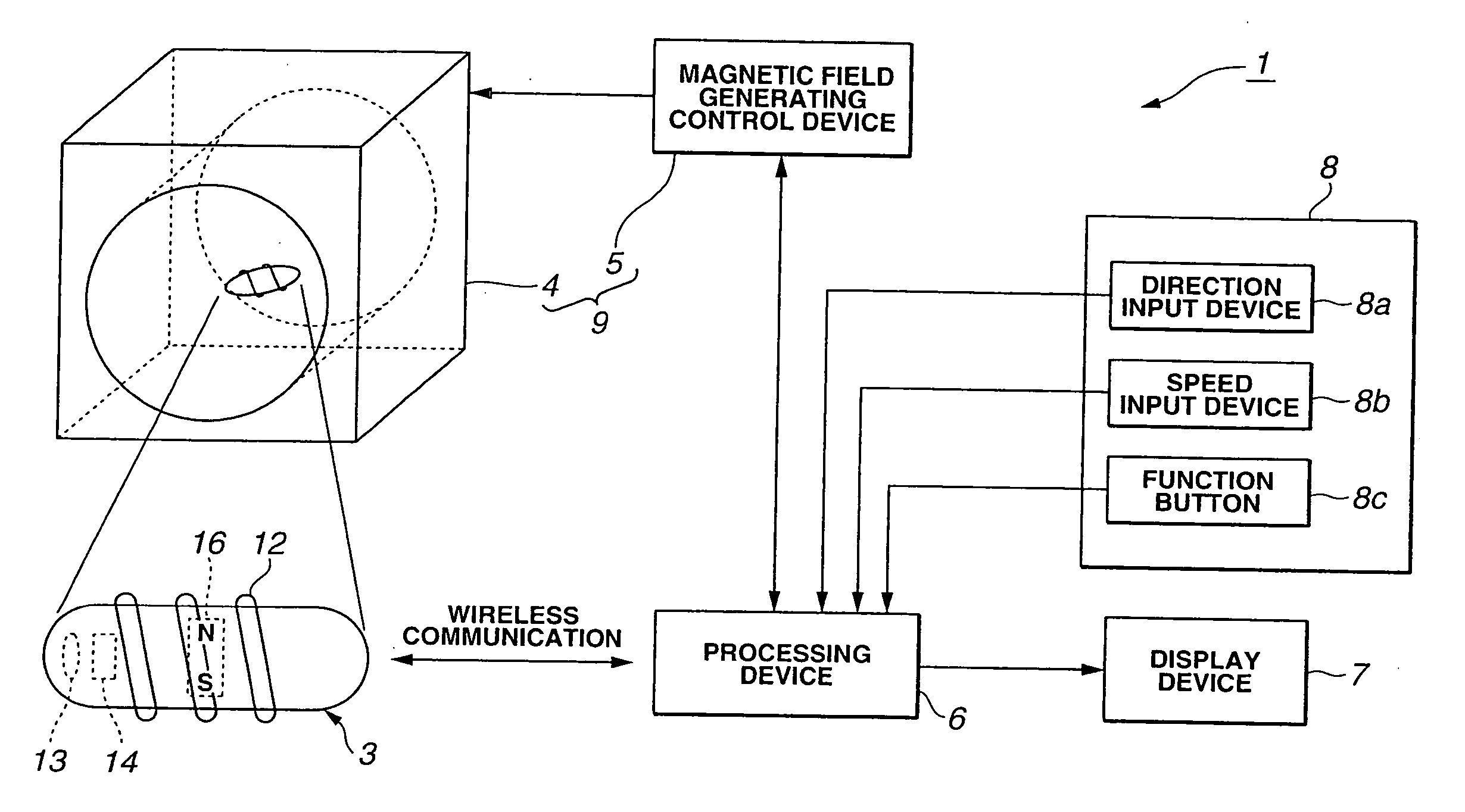
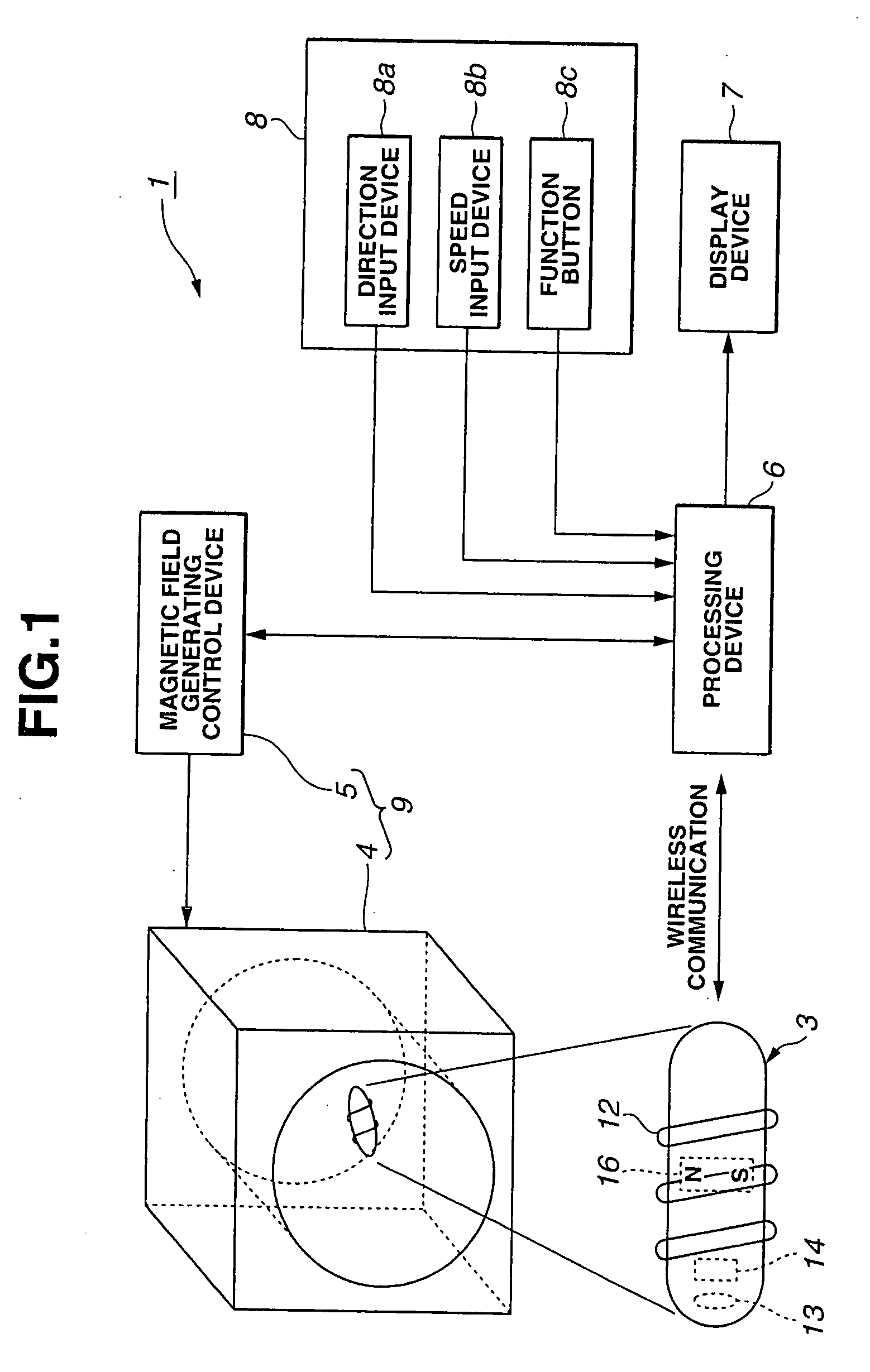
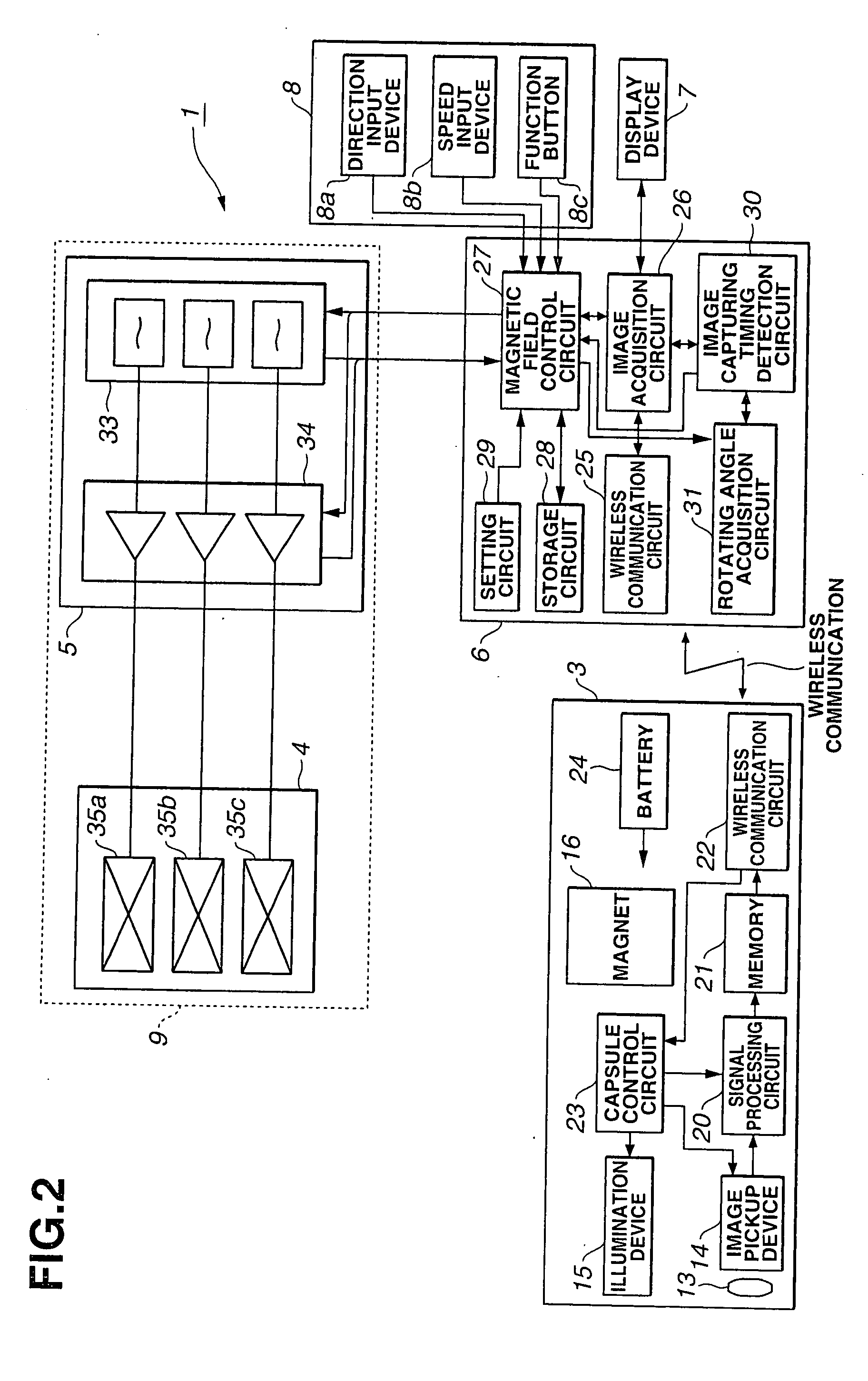
[0086] As shown in FIGS. 1 and 2, a capsule medical system 1 according to the embodiment 1 of the present invention includes: a capsule medical device (a capsule endoscope) 3 (which will be simply referred to as “capsule” hereafter) serving as a capsule endoscope, which is inserted to the body cavity of an unshown subject from the mouth or anus, and which allows image capturing, diagnosis, and treatment and the like within the body cavity; and a magnetic field generating apparatus 9 which is positioned so as to surround the subject, i.e., is positioned outside of the subject. The magnetic field generating apparatus 9 comprises: a rotational magnetic field generating device 4 for applying a rotational magnetic field to the capsule 3, and a magnetic field generating control device (or power supply control device) 5 for controlling supply of the driving current for generating the rotational m...

embodiment 2

[0169] Next, description will be made regarding an embodiment 2 according to the present invention with reference to FIGS. 10 and 11. FIG. 10 shows a configuration of a capsule medical system 1B according to the embodiment 2 of the present invention.

[0170] The capsule medical system 1B comprises: a capsule 3B; the magnetic field generating apparatus 9; a processing device 6B; the display device 7; and the operation input device 8.

[0171] The capsule 3B has generally the same configuration as that of the capsule 3 shown in FIG. 2, except for a configuration in which the captured image signal captured by the image pickup device 14 is transmitted in the form of an analog signal modulated by the wireless communication circuit 22. That is to say, the capsule 3B has generally the same configuration as that shown in FIG. 2, except for not including the signal processing circuit 20 for A / D conversion, image-data compression, and so forth, and the memory 21.

[0172] Furthermore, the capsule ...

embodiment 3

[0184] Next, description will be made regarding an embodiment 3 according to the present invention with reference to FIGS. 12 and 13. FIG. 12 shows a configuration of a capsule medical system 1C according to the embodiment 3 of the present invention.

[0185] While the capsule 3C according to the present embodiment has only a function for transmitting the captured image in the same way as the capsule 3B shown in FIG. 10, the capsule 3C includes the signal processing circuit 20 and the memory 21, and transmits the compressed image data in the same way as the embodiment 1.

[0186] Furthermore, with the present embodiment, after a predetermined period of time following transmission of the compressed image data, the next image capturing is started. That is to say, the capsule 3C performs the next image-capturing operation in parallel with the operation of the processing device 6C for performing decompression of compressed image data and so forth.

[0187] Furthermore, the capsule control cir...


PUM


Abstract

A medical system includes: a medical device to be inserted into the body cavity; a rotating device for the medical device for rotating the medical device around the insertion axis; an image pickup device provided to the medical device; and an image capturing timing detection device for detecting a signal regarding image capturing timing performed by the image pickup device. Furthermore, the medical system includes: a rotating angle acquisition device for acquiring the rotating angle of the rotating device for the medical device regarding the image capturing timing in response to the output of the image capturing timing detection device; and an image acquisition device for performing rotation processing for the image captured by the image pickup device based upon the information regarding the rotating angle acquired by the rotating angle acquisition device, thereby acquiring the image subjected to a rotation processing.

Description

TECHNICAL FIELD [0001] The present invention relates to a medical system including a medical device having a function of generating propelling force within the body cavity by rotation thereof. BACKGROUND ART [0002] Various types of medical devices have been proposed, each of which is inserted into the body cavity, and has a function for generating propelling force and so forth by rotation thereof, thereby allowing examination of the body cavity. [0003] For example, Japanese Unexamined Patent Application Publication No. 2003-299612 discloses a capsule endoscope system having a function for guiding a capsule endoscope within the lumen by applying a rotational magnetic field so as to rotate the capsule endoscope. [0004] In the prior art disclosed in the above Patent document, the image data acquired by the capsule endoscope is transmitted to an image processing device outside of the body. The image processing device stores the received image data and the data of the rotational magnetic...

Claims


Application Information

Patent Timeline
IPC IPC(8): A61B1/00
CPCA61B1/00016A61B1/0008A61B1/00156A61B1/00158A61B5/7232A61B1/273A61B5/062A61B5/073A61B2019/2253A61B1/041A61B34/73
Inventor UCHIYAMA, AKIOAOKI, ISAOTANAKA, SHINSUKETAKIZAWA, HIRONOBUKAWANO, HIRONAO
Owner OLYMPUS CORP
Learn More