Automatic separator/extractor and method of controlling same

a technology of automatic separator and extractor, which is applied in the direction of centrifuges, laboratory glassware, instruments, etc., can solve the problems of high risk of cross contamination, difficult operation involving delicate operator skill, and high risk of personnel safety, and achieves high accuracy and high efficiency of large-volume liquid processing. , the effect of high accuracy

Inactive Publication Date: 2006-05-25
PRECISION SYST SCI
View PDF8 Cites 29 Cited by
  • Summary
  • Abstract
  • Description
  • Claims
  • Application Information

AI Technical Summary

Benefits of technology

[0057] According to the respective aspects of the invention, it is possible to use a dispensing device which uses pipette tips, so that highly accurate dispensation of small amounts of liquid is possible, to thereby enable processing at a high accuracy.
[0058] According to the respective aspects of the invention, it is possible to use a microplate having a large number of wells, and perform drawing and discharging processing in large quantities altogether, to thereby enable efficient and speedy processing of large quantities of liquid, to enable correspondence of large scale simulation base sequences.

Problems solved by technology

However conventionally, in the case of performing the above processing, the precipitate obtained as a result of reaction or extraction is not always limited to a stabilized solid mass, the there are many cases where this must be handled as a turbid unstable mass.
Hence this is a difficult operation involving delicate skill of the operator.
Furthermore, there is the problem that the water adheres to the surface of the plate, so that cross contamination is likely to occur, and safety to personnel is likely to be compromised.
Thirdly, to be able to have a comparatively simple structure to thereby achieve a reduction in manufacturing costs, and take up a minimum space by making this compact.

Method used


Image

  • Automatic separator/extractor and method of controlling same
  • Automatic separator/extractor and method of controlling same
  • Automatic separator/extractor and method of controlling same

Examples


Embodiment Construction

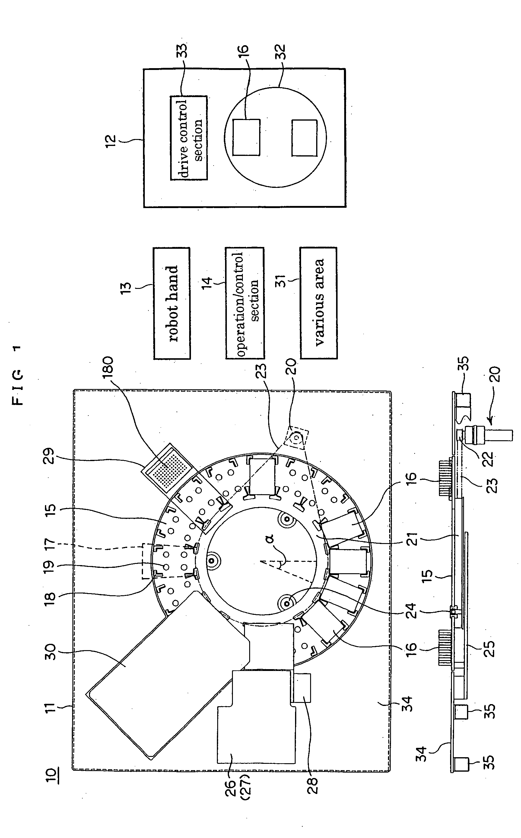
[0067] An separator / extractor according to embodiments of the present invention is described with reference to FIG. 1 through FIG. 8. The present invention is not limited to the embodiments apart from where especially specified. FIG. 1 shows the whole of the separator / extractor according to an embodiment.

[0068] The automatic separator / extractor 10 has a processing section 11 for extraction or the like (referred to hereunder as an extraction processing section 11), a centrifugal separation section 12 as a separator, a robot hand 13 as a vessel moving device, and an operation / control section 14. The extraction processing section 11 has a turntable 15 formed in an annulus ring which is rotatably driven. The turntable 15 is provided with a plurality of mounting sections 17 (16 in this example) for mounting microplates 16 (hereunder “plates”) having deep wells, so as to subtend therebetween base center angles (denoted α in the figure) or center angles which are multiples of these at eve...


PUM

PropertyMeasurementUnit
diameteraaaaaaaaaa
diameteraaaaaaaaaa
angleaaaaaaaaaa

Abstract

The invention relates to an automatic separator/extractor and a method of controlling same, with the object, particularly in all manner of fields such as medical science, agricultural science, scientific fields, or pharmaceuticals, of being able to achieve at high speed and accuracy, extraction or separation of precipitate or supernatant at a high quality, accuracy and reliability, above that which can be achieved by manual means. The construction has a conveying device for conveying a mounted vessel along a closed path, a dispensing section for dispensing a reagent or the like into the vessel mounted on the conveying device, a liquid processing section for removing and/or extracting liquid other than a precipitate inside the vessel mounted on the conveying device, a separator for performing separation with respect to the contents inside a vessel which is mounted on the conveying device and/or a vessel which is installed away from the conveying device, a vessel moving device for bringing in and taking out the vessel with respect to the conveying device and/or separator, and an operation/control section for performing operation and control with respect to the conveying device, the dispensing section, the liquid processing section, the vessel moving device, and the separator.

Description

CROSS-REFERENCE [0001] This application is a continuation of U.S. Ser. No. 09 / 807,596, filed Apr. 13, 2001, which claims priority to International Application No. PCT / JP99 / 05648, filed Oct. 13, 1999, which claims priority to Japanese Patent Application No. 10-291159, filed Oct. 13, 1998.TECHNICAL FIELD [0002] The present invention relates to an automatic separator / extractor and a method of controlling same. Particularly, the present invention relates to an automatic separator / extractor and a method of controlling same, applicable to medical treatment, inspection, diagnosis, medical care, research, quantitative analysis, qualitative analysis and so on, which in order to perform separation, extraction or recovery of immune substances such as antibodies or antigens, genetic substances (DNA, RNA, m-RNA and so on), bacillus, and other useful substances such as medicines, or target substances, in all manner of fields such as medical science, agricultural science, scientific fields, pharma...

Claims


Application Information

Patent Timeline
Patent Type & Authority Applications(United States)
IPC IPC(8): B01L3/00G01N35/00B03C1/00B04B11/00G01N1/10G01N33/543G01N35/02
CPCG01N35/0099G01N35/025G01N2035/00504
Inventor TAJIMA, HIDEJISAGAWA, NORIHISASATO, TOYOSAKUMORITA, MASATAKAHAYASAKA, HIROSHISATO, KOUJITAKAHASHI, KAHORU
Owner PRECISION SYST SCI
Why Eureka
Try Eureka