Floorboard and method for manufacturing thereof

Active Publication Date: 2008-01-03
VÄLINGE INNOVATION AB
View PDF99 Cites 94 Cited by
  • Summary
  • Abstract
  • Description
  • Claims
  • Application Information

AI Technical Summary

Benefits of technology

[0017] An object of the present invention is to provide floorboards which can be joined mechanically to form a floating flooring wit

Problems solved by technology

Shrinkage and swelling occur under the baseboards and the joints between the floorboards are tight.
Laying is complicated and the flooring cannot be removed without being damaged.
A great drawback of such floating floors with a hard surface of wood

Method used


Image

  • Floorboard and method for manufacturing thereof
  • Floorboard and method for manufacturing thereof
  • Floorboard and method for manufacturing thereof

Examples


Embodiment Construction

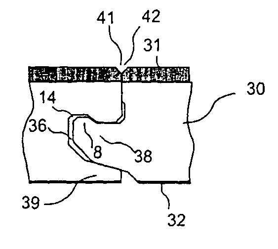
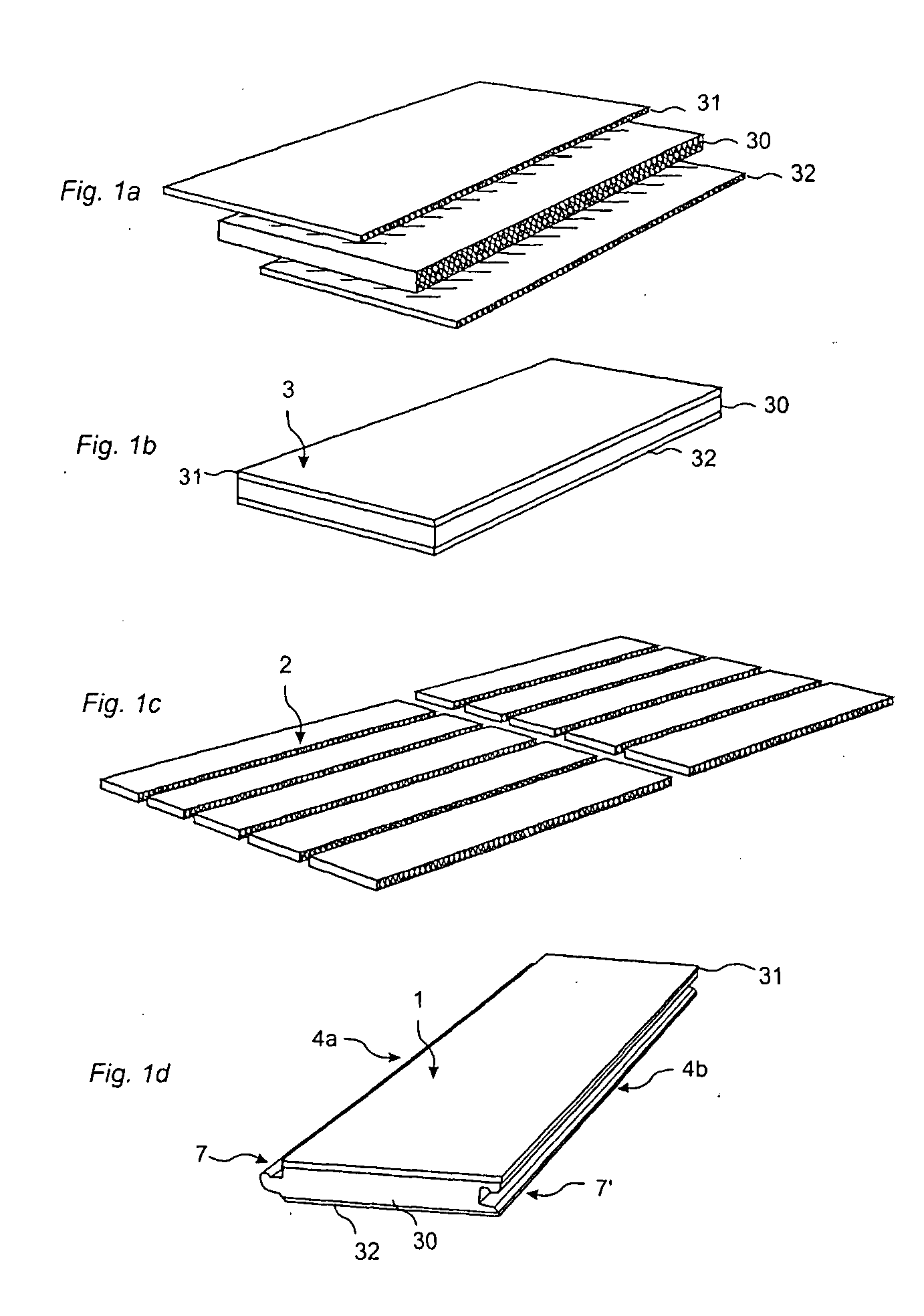
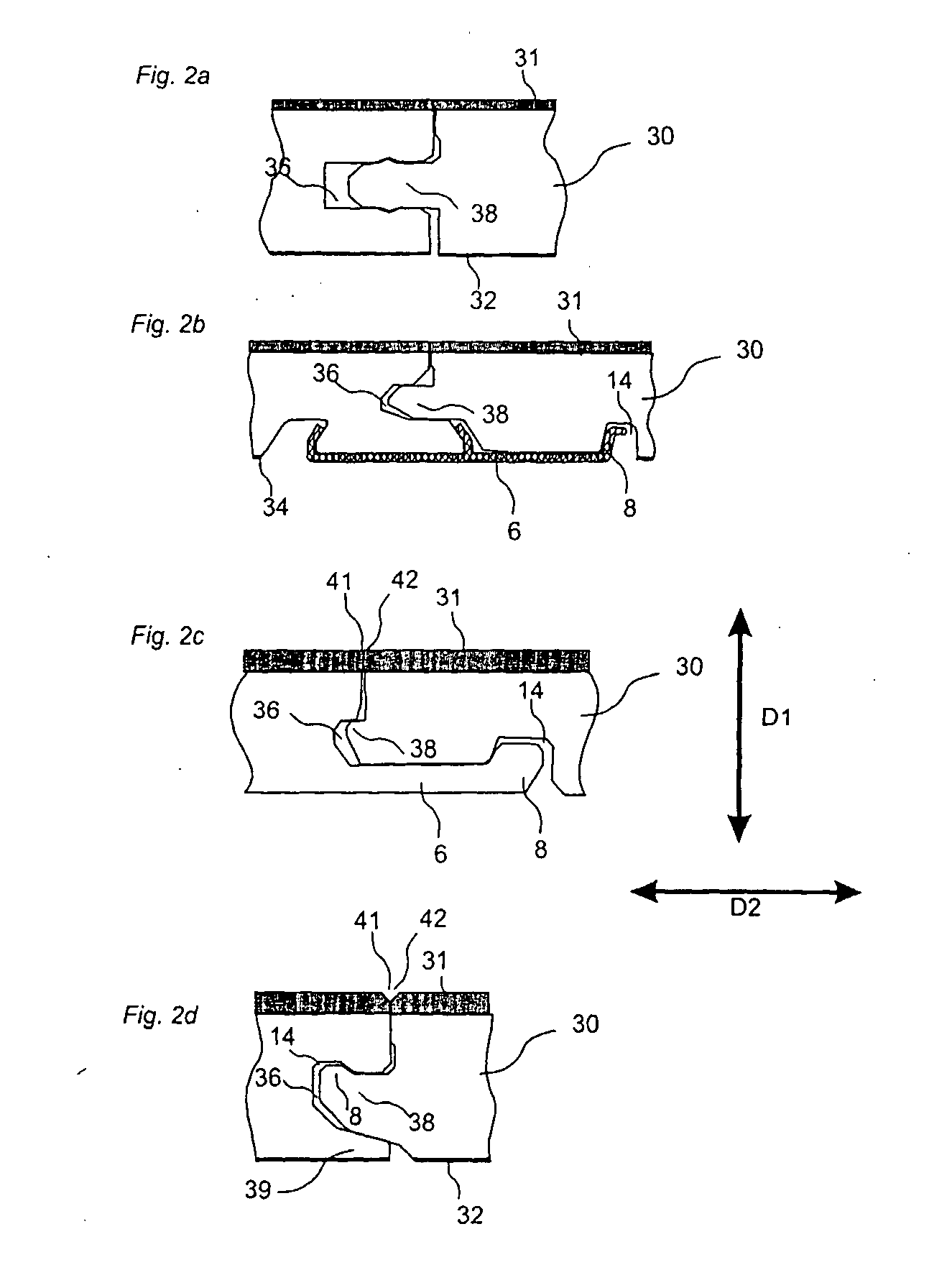
[0041]FIGS. 1a-d illustrate the manufacture of a floorboard according to an embodiment of the invention. A layer 31, which in this embodiment consists of needle felt, is joined, for instance, by gluing to a core 30. This core may consist of, for example, particle board, fiberboard, such as MDF, HDF, plywood or the like. A lower layer, for instance a balancing layer 32, can be applied to the rear side to prevent cupping. This rear layer can also be a soft material, such as foam, needle felt, cardboard or the like, which levels irregularities in the subfloor and which improves the reduction of sound. This lower layer is in some applications not necessary. The floor element 3, which may have a thickness of e.g. 5-20 mm, is then divided into a plurality of floor panels 2. These panels are then machined and joint edge portions are formed so as to constitute a mechanical joint system 7, 7′. An example of such a joint system on the long sides 4a and 4b is shown in FIG. 1d. The floorboards ...


PUM

PropertyMeasurementUnit
Flexibilityaaaaaaaaaa

Abstract

Floorboards with a surface of flexible fibers for laying a mechanically joined floating floor, and methods for manufacturing and profloorings containing such floorboards.

Description

CROSS REFERENCE TO RELATED APPLICATIONS [0001] The present application claims the benefit of Swedish Patent Application No. SE 0300479-3, filed in Sweden on Feb. 24, 2003, and U.S. Provisional Application No. 60 / 456,957, filed in the United States on Mar. 25, 2003. The contents of SE 0300479-3 and U.S. 60 / 456,957 are incorporated herein by reference.BACKGROUND OF INVENTION [0002] 1. Technical Field [0003] The invention relates generally to the technical field of floorboards. The invention concerns floorboards with a sound-absorbing surface of fibers which can be joined mechanically in different patterns. The invention also concerns methods for manufacturing such floorboards. The invention is particularly suited for use in floating floors. [0004] 2. Field of Application [0005] The present invention is particularly suited for use in floating floors with mechanical joint systems. Such floors often consist of a surface layer of laminate or wood, a core and a balancing layer and are form...

Claims


Application Information

Patent Timeline
IPC IPC(8): E04F15/22A47G27/02B27F1/04B27F1/06B27M3/04B27M3/08B32B21/10E04FE04F15/02E04F15/04
CPCA47G27/0293Y10T29/49616B27F1/06B27M3/04B27M3/08B32B21/10E04F15/02E04F15/04E04F2201/0153E04F2201/023E04F2201/026E04F2201/03E04F2201/05E04F2201/0517E04F15/02038E04F15/102E04F15/107E04F15/181Y10T29/49623B27F1/04E04F15/041E04F15/02194E04F15/042E04F15/105B32B5/26B32B3/06B32B2307/102B32B2471/00E04F15/186
Inventor PERVAN, DARKO
Owner VÄLINGE INNOVATION AB
Why Eureka
Try Eureka