Parking lock mechanism for a transmission and transmission incorporating such a parking lock mechanism

a technology of parking lock and transmission, which is applied in the direction of mechanical control devices, instruments, process and machine control, etc., can solve the problems of affecting the operation of the transmission, and requiring a large installation space for known parking locks, so as to prevent faulty assembly, facilitate handling, and prevent loosening.

Inactive Publication Date: 2008-01-03
ZF FRIEDRICHSHAFEN AG
View PDF6 Cites 3 Cited by
  • Summary
  • Abstract
  • Description
  • Claims
  • Application Information

AI Technical Summary

Benefits of technology

[0010]The parking lock mechanism according to the invention has the advantage that the leaf spring, on one hand, is easier to handle than a spiral or tension spring, making assembly easier and preventing faulty assembly and, on the other hand, requires less installation space. The latter can be particularly attributed to the fact that a leaf spring has a very flat design and does not need to be located on the axis of rotation of the pawl nor supported on a housing part.
[0011]A preferred configuration of the parking lock mechanism, according to the invention, includes a housing. This can be, for example, a housing of the parking lock mechanism itself or the transmission housing. In this configuration, the leaf spring is attached to the housing. Contrary to the state of the art, the spring element, in the form of the torsion spring, is therefore not attached to the axis of rotation or the pivot pin of the pawl, while the leg of the torsion spring is supported on the housing. Instead, the leaf spring is both attached to and supported on the housing. This has the advantage that installation space is available in the region of the axis of rotation of the pawl, which can be used particularly effectively for further measures to prevent tilting of the pawl.
[0012]In another preferred configuration of the parking lock mechanism according to the invention, the leaf spring is attached in a form-fit manner to the housing. The leaf spring can simply be inserted, for example, into an appropriately shaped recess on the housing to achieve the fastening effect. In any case, assembly is considerably easier than with a screw connection or similar.
[0013]The above advantage is particularly evident in another preferred configuration of the parking lock mechanism, according to the invention, where the leaf spring has an arched end, which is inserted in a correspondingly arched cavity on the housing to fasten the leaf spring.

Problems solved by technology

For example, the known parking locks require a large installation space.
Furthermore, the complexity of the spiral or torsion springs, which are also difficult to manage during assembly, can result in faulty assembly, which can ultimately result in a loosening of the spring or torsion spring during operation.
Furthermore, the spiral or torsion springs tend to break during operation, which can ultimately lock the transmission permanently.
In addition, the measures aimed at preventing the tilting of the pawl, which may occur particularly in the case of axial pawl actuation, result in increased expenses in the known parking lock mechanisms.

Method used


Image

  • Parking lock mechanism for a transmission and transmission incorporating such a parking lock mechanism
  • Parking lock mechanism for a transmission and transmission incorporating such a parking lock mechanism

Examples


Embodiment Construction

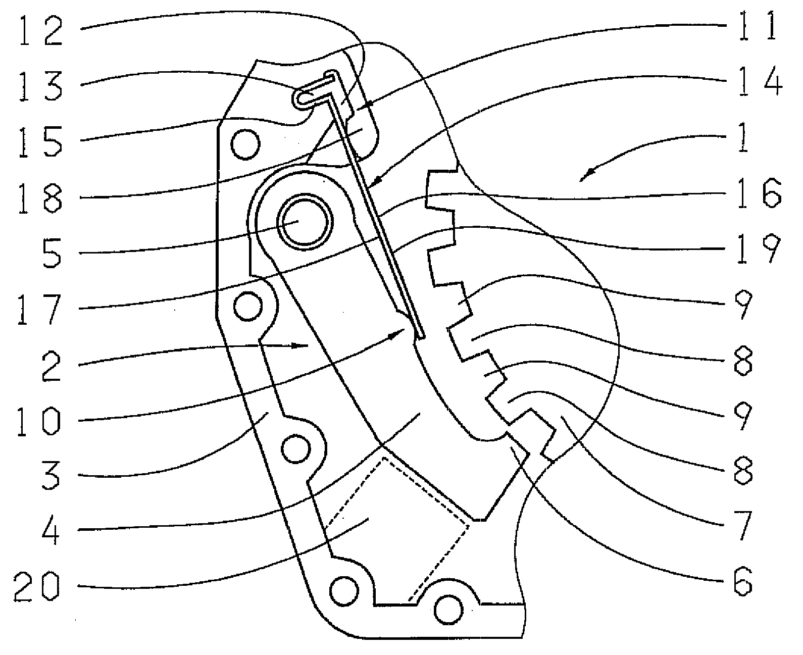
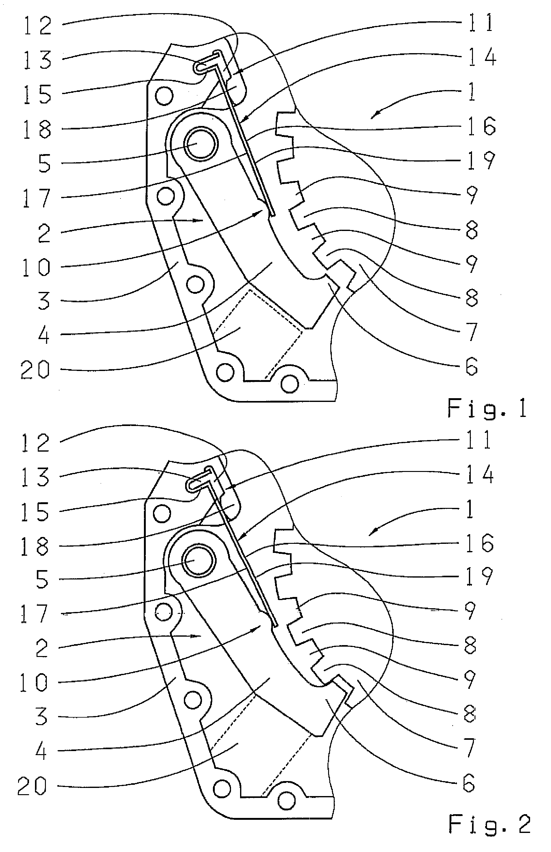
[0029]FIG. 1 shows one section of a transmission 1 in which one configuration of the parking lock mechanism 2 according to the invention is incorporated. The transmission 1 comprises a housing 3, which encloses both the transmission components and the parking lock mechanism 2.

[0030]The parking lock mechanism 2 first of all comprises a pawl 4, one end of which is connected to an axis of rotation 5 about which the pawl 4 can pivot. The axis of rotation 5 is disposed on the housing 3. On the side of the pawl 4, facing away from the axis of rotation 5, a protruding detent tooth 6 is provided. The detent tooth 6 faces the circumference of a parking lock gear wheel 7, which is non-rotatably connected to the output shaft (not shown) of the transmission 1 and which has on its circumference further detent teeth 8 with detent cavities 9 located between them. The output shaft of the transmission 1 and the axis of rotation 5 of the pawl 4 are arranged parallel to each other. A protrusion 10 is ...


PUM


Abstract

The present invention relates to a parking lock mechanism (2) for a transmission (1), comprising a pawl (4), which can pivot from a neutral position into a locking position in which the transmission (1) is locked, whereby the pawl (4) is prestressed in the neutral position by way of a spring element. According to the invention, the spring element is a leaf spring (14). The present invention furthermore relates to a transmission (1) incorporating such a parking lock mechanism (2).

Description

[0001]This application claims priority from German Application Serial No. DE 10 2006 030 156.0 filed Jun. 29, 2006.FIELD OF THE INVENTION[0002]The present invention relates to a parking lock mechanism for a transmission, comprising a pawl, which can pivot from a neutral position into a locking position in which the transmission is locked, whereby the pawl is prestressed in the first position by way of a spring element. Furthermore, the present invention relates to a transmission incorporating such a parking lock mechanism.BACKGROUND OF THE INVENTION[0003]From the state of the art, various parking lock mechanisms for automatic transmissions are known. These frequently comprise a pivotable pawl and a parking lock gear wheel, which is located, non-rotatably, on an input shaft of the transmission, the shaft of which is to be locked. The pawl can be pivoted about an axis of rotation from a neutral position in which the pawl does not mesh with the parking lock gear wheel, into a locking p...

Claims


Application Information

Patent Timeline
Patent Type & Authority Applications(United States)
IPC IPC(8): F16H63/38
CPCF16H63/3416Y10T74/20104F16H63/3425
Inventor REICHERT, HEINZLANGWALD, OLAF
Owner ZF FRIEDRICHSHAFEN AG
Why Eureka
Try Eureka