Drain Valve

a technology of drain valve and drain plug, which is applied in the direction of shafts, bearings, lubrication elements, etc., can solve the problems of oil accumulation of small contaminants lost or misplaced oil plugs, etc., and achieve the effect of easy unseated

Inactive Publication Date: 2008-01-03
ILLINOIS TOOL WORKS INC
View PDF17 Cites 37 Cited by
  • Summary
  • Abstract
  • Description
  • Claims
  • Application Information

AI Technical Summary

Benefits of technology

[0016]An advantage of the present invention, in one aspect thereof, is providing a drain valve for motor vehicle oil pans that can be used in stamped metal oil pans, cast aluminum oil pans and molded oil pans made of plastics or other materials as stamped, as cast or as molded, without the need for secondary operations to adapt the oil pan once provided.
[0017]Another advantage of the present invention, in another aspect thereof, is providing an oil pan drain valve that includes a drain plug that can be opened and closed with less than one full rotation, and that remains secured to a drain aperture even when loosened and while allowing oil flow from the oil pan, yet can be removed and replaced if necessary.
[0018]Yet another advantage of the present invention, in yet another aspect thereof, is providing a drain valve for oil pans that is not damaged by over tightening.
[0019]A still further advantage of the present invention in a still further aspect thereof is providing a drain valve for a motor vehicle oil pan that can be unseated easily to initiate drainage, and that can be configured for controlling and directing the direction of oil flow from the oil pan at an acceptable flow rate.
[0020]Other features and advantages of the invention will become apparent to those skilled in the art upon review of the following detailed description, claims and drawings in which like numerals are used to designate like features.

Problems solved by technology

Filters and screens are provided for removing contaminants from the oil, but over time the oil accumulates small contaminants that aren't removed.
While oil pans, drain plugs and threaded interrelationships therebetween have been used effectively for many years, they are not without drawbacks.
For example, when the plug is removed from the drain outlet, it can be lost or misplaced.
A lost or misplaced oil plug can be problematic in that the typical vehicle owner will not have suitable replacement plugs handy.
Traveling to a parts store for a replacement plug can be both inconvenient and time consuming, since the vehicle cannot be operated without the drain plug in place.
Over time, the threads in the drain outlet or on the plug can be damaged from repeated use, over-tightening, misaligned threading and wear from dirt and grime on the threads.
Wear in the threads of the outlet and / or the plug can result in oil leakage.
Further, alternative materials are being used, including various plastics which may not thread well and which may not respond well to frequent threading into and out of by the drain plug.
Brass inserts can be used but may allow oil to seep through welded regions and may not be cost-effective.
Plastic threaded plugs can be over torqued easily, or otherwise damaged, and may be replaced by metal plugs during oil changes causing increased where in the threads of the drain outlet.
Accordingly, sealing the oil drain outlet in plastic oil pans has presented difficulties
Other disadvantages of common threaded drain plugs and drain holes include difficulty in removing the drain plug if overly tightened and potential damage to the plug and / or the threads in the oil pan if tightened excessively.
While the plug can be replaced inexpensively, if the threads in the oil pan are damaged repair or replacement can be more costly and time consuming.

Method used


Image

  • Drain Valve
  • Drain Valve
  • Drain Valve

Examples


Embodiment Construction

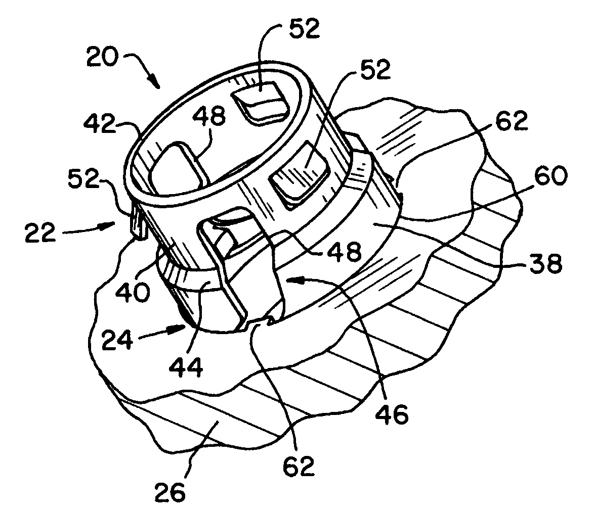
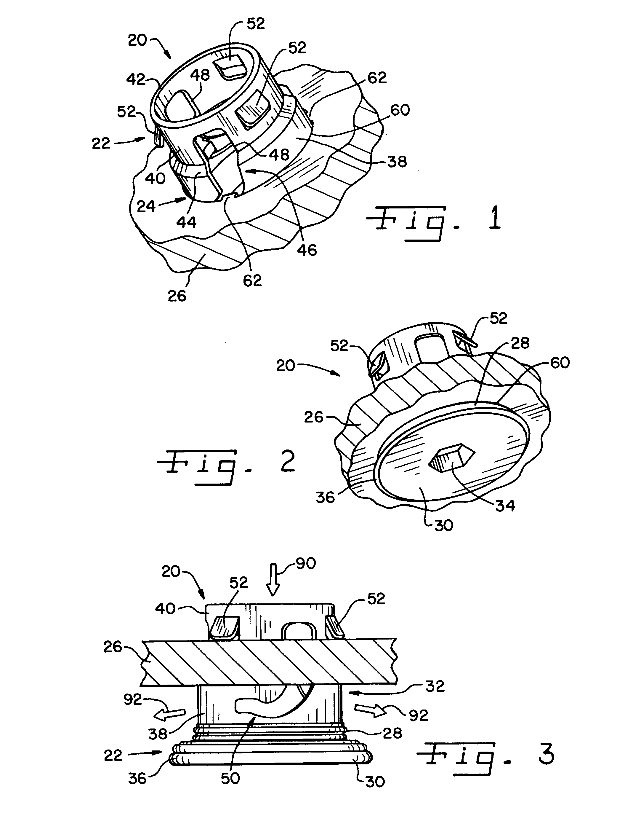
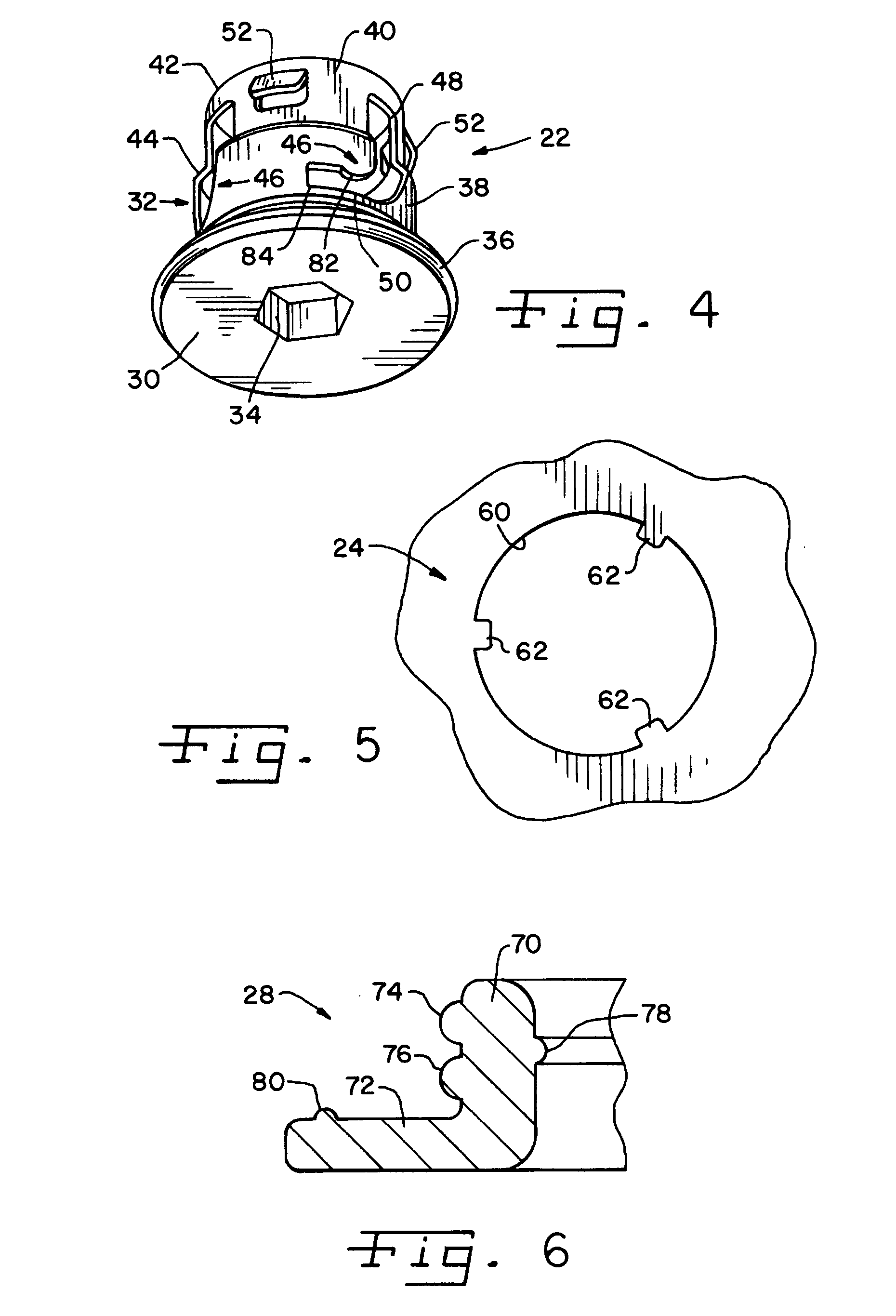
[0037]Referring now more specifically to the drawings and to FIGS. 1, 2 and 3 in particular, a drain valve 20 in accordance with the present invention is shown. Drain valve 20 includes a plug 22, an aperture 24 provided in an oil pan 26 and a seal 28 disposed between plug 22 and aperture 24. Plug 22 and aperture 24 can be made out of various materials suitable for the application, including metals and plastics. Plug 22 and aperture 24 can be of the same material or can be of different materials.

[0038]Plug 22 includes a head 30 and a body 32 extending from one side of head 30. Head 30 defines a tool receiver 34, which in the exemplary embodiment is in the form of a hex-shaped cavity 34 for receiving a driving tool to rotate plug 22 relative to aperture 24. It should be understood that tool receiver 34 in the nature of a cavity 34 as shown for the exemplary embodiment can be cavities of other shapes for receiving other types of tools, including various sizes and styles of male drivers...


PUM


Abstract

A drain valve for an oil pan of a vehicle lubrication system includes an aperture and a drain plug. The drain plug is rotatable relative to the aperture between closed and opened positions with less than a full rotation of the plug. The plug remains secured to the aperture even when the valve is opened.

Description

CROSS-REFERENCE TO RELATED APPLICATIONS[0001]The present regular U.S. patent application claims the benefits of U.S. Provisional Application Ser. No. 60 / 817,432; filed on Jun. 29, 2006.FIELD OF THE INVENTION[0002]The present invention relates generally to drain valves, and, more particularly, the present invention pertains to oil pan drain valves for motor vehicle engine lubrication systems.BACKGROUND OF THE INVENTION[0003]Automobile engine lubrication systems include an oil reservoir, often referred to as an oil pan, that holds a volume of oil which is picked up and circulated through the vehicle engine by a circulating pump and oil pickup assembly. Filters and screens are provided for removing contaminants from the oil, but over time the oil accumulates small contaminants that aren't removed. As a result, routine engine maintenance includes frequent, periodic oil changes during which the used oil is drained and replaced for better lubrication performance.[0004]It is known to provi...

Claims


Application Information

Patent Timeline
Patent Type & Authority Applications(United States)
IPC IPC(8): F16C3/14
CPCF01M2011/0416F01M11/0408
Inventor STLASKE, WILLIAM G.JONES, JAMES D.HEAVENS, GLENN G.HOLT, JASONBOVEN, ALBERT V.
Owner ILLINOIS TOOL WORKS INC
Why Eureka
Try Eureka