
High-speed polarizing device and high-speed birefringence measuring apparatus and stereoscopic image display apparatus utilizing the polarizing device

a polarizing device and birefringence technology, applied in the direction of optical radiation measurement, instruments, television systems, etc., can solve the problems of large area, high measurement speed, and inability to set the maximum measurement speed, etc., to achieve high speed, short time, and high quality

Inactive Publication Date: 2008-01-03
FUJIFILM CORP
View PDF1 Cites 10 Cited by
  • Summary
  • Abstract
  • Description
  • Claims
  • Application Information

AI Technical Summary

Benefits of technology

[0031]In this high-speed polarizing device, the polarized light radiating units can switch polarizing directions at a high speed. As a result, when birefringence characteristics of a sample are analyzed, the measurement can be carried out at a high speed even if the sample has a large area. Even in the case of measurement of an object which undergoes state changes in a short time, measuring intervals can be made shorter to allow state changes in a short time to be accurately measured.(8) A high-speed birefringence measuring apparatus characterized in that it includes:
[0034]In this high-speed polarizing device, the polarization direction splitting units can switch polarizing directions at a high speed. As a result, when birefringence characteristics of a sample are analyzed, the measurement can be carried out at a high speed even if the sample has a large area. Even in the case of measurement of an object which undergoes state changes in a short time, measuring intervals can be made shorter to allow state changes in a short time to be accurately measured.(9) A stereoscopic image display apparatus characterized in that it includes:
[0039]Since the high-speed polarizing device allows polarization directions to be switched at a high speed, contents displayed can be changed at a high speed, which makes it possible to provide a stereoscopic image display function with higher quality.
[0040]The invention provides a high-speed polarizing device capable of switching polarization directions at a high speed. When the device is used in a birefringence measuring apparatus, measurement can be carried out at a high speed even in the case of an object having a large area. Even in the case of measurement of an object which undergoes state changes in a short time, measuring intervals can be made shorter to allow state changes in a short time to be accurately measured. When the high-speed polarizing device is used to switch states of polarization in displaying three-dimensional images, since polarization directions can be switched at a high speed, a stereoscopic image display function with higher quality can be provided.

Problems solved by technology

Therefore, the speed of measurement of a state of polarization cannot be set higher than the maximum rotating speed of the motor, and a limit has been placed on efforts toward higher measuring speeds even if a difference (an increase) in the rotating speed achievable with a power transmission mechanism is taken into consideration.
As a result, a great amount of time has been required for measurement of a large area.
Further, when measurement is conducted on an object which undergoes state changes in a short time, problems have arisen including the impossibility of measuring such state changes in a short time attributable to measuring intervals which cannot be made shorter.

Method used


Image

  • High-speed polarizing device and high-speed birefringence measuring apparatus and stereoscopic image display apparatus utilizing the polarizing device
  • High-speed polarizing device and high-speed birefringence measuring apparatus and stereoscopic image display apparatus utilizing the polarizing device
  • High-speed polarizing device and high-speed birefringence measuring apparatus and stereoscopic image display apparatus utilizing the polarizing device

Examples


embodiment 1

[0142]Embodiments of the invention will now be described.

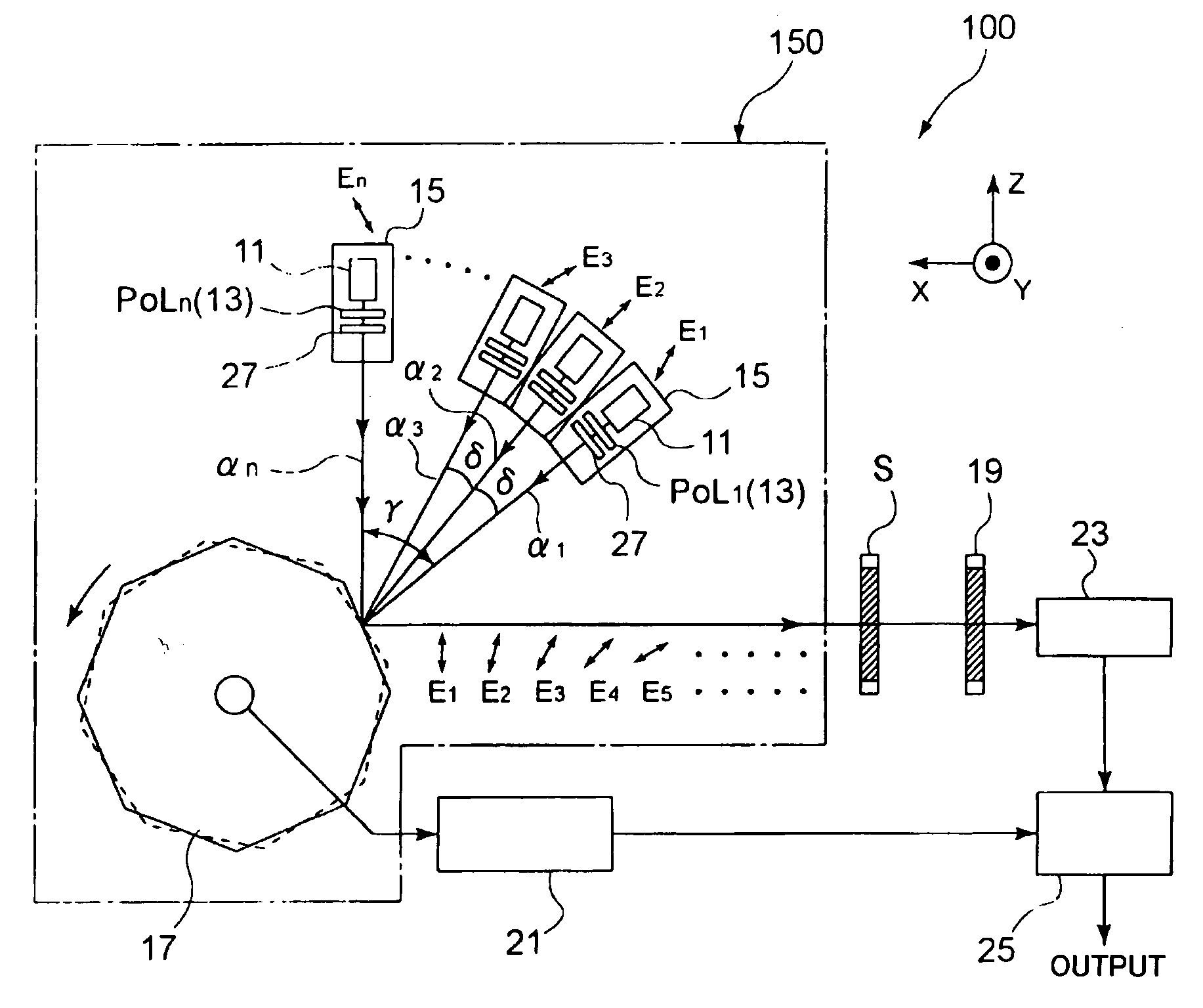
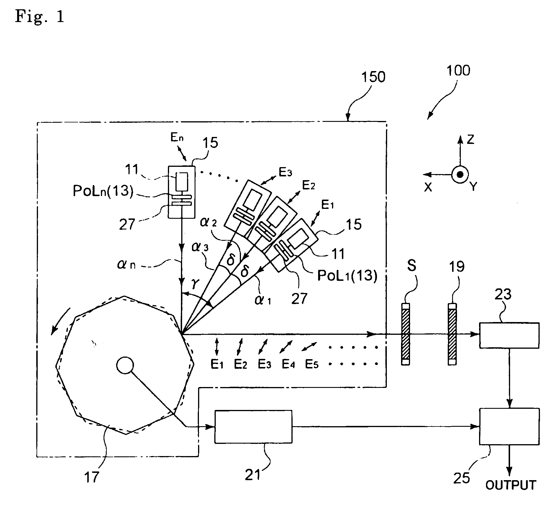
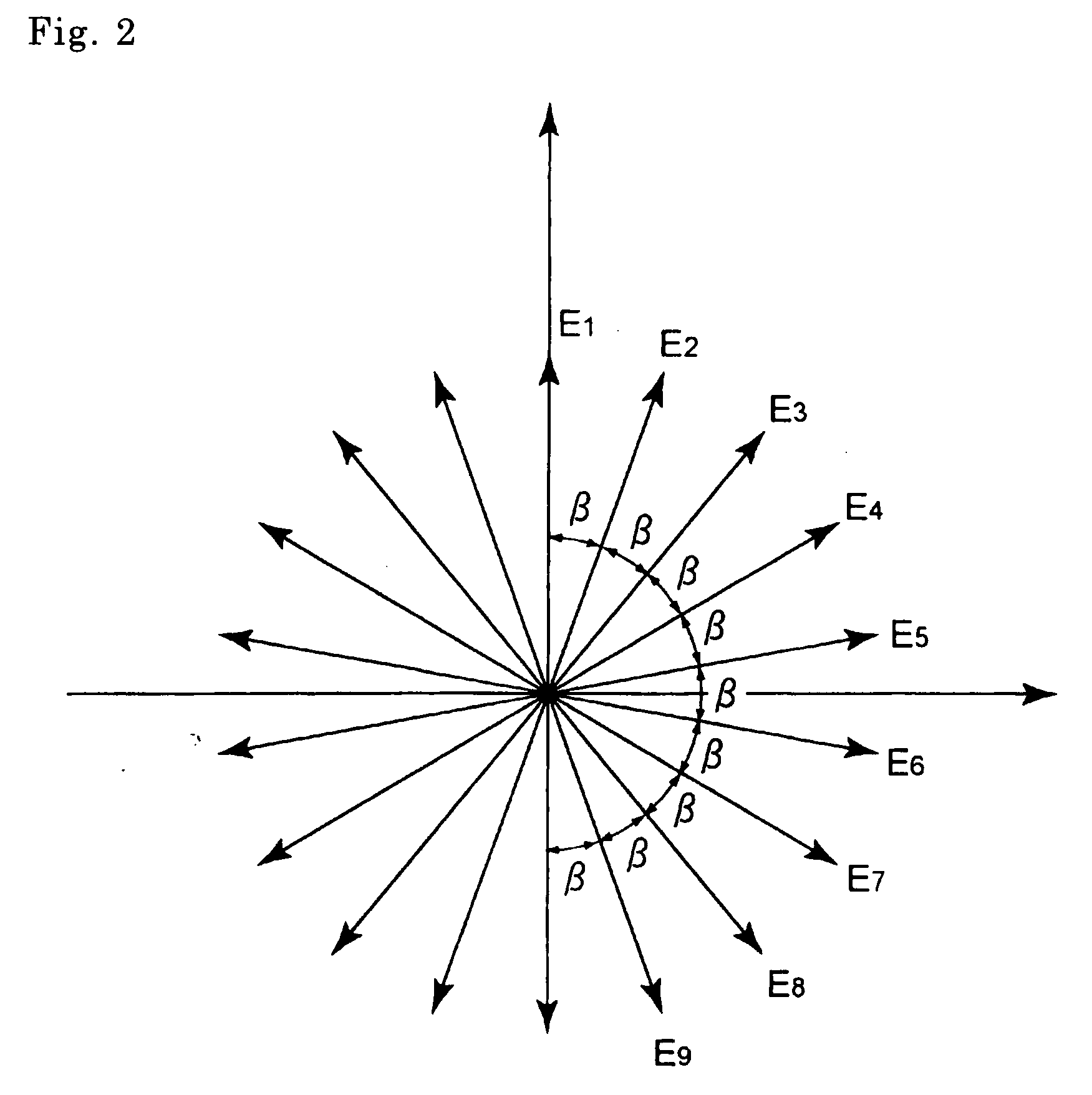
[0143]The birefringence of an optical film was measured according to the rotary polarizer method using the birefringence measuring apparatus 100 shown in FIG. 1. Nine laser generators (having a wavelength of 633 nm) were used as the light sources 11, and a polarizer 13 was disposed immediately behind each light source 11, the polarization directions of each pair of adjacent polarizers being at an angle of 20° to each other to define a total angular range from 0° to 160°. A λ / 4 plate was used as the first compensator 27, and the in-plane angle of the first compensator 27 was adjusted to compensate for changes in polarization attributable to reflection at the polygon mirror 17. The in-plane angle of the first compensator 27 was adjusted by fixing the polygon mirror 17 at the angle at which light from a particular light source impinged upon the light-receiving device 23 and rotating the analyzer 19 with the sample S removed to me...

embodiment 2

[0147]The birefringence of an optical film was measured according to the rotary analyzer method using the birefringence measuring apparatus 200 shown in FIG. 3. A single laser generator (633 nm) was used as the light source 31, and a polarizer 33 having a transmission axis direction at 45° was disposed immediately behind the same. A sample S was placed behind the polarizer 33, and light transmitted through the sample S was sequentially projected along nine optical axes α1 to αn by the polygon mirror 17 having eight surfaces. The analyzers 37 were disposed immediately before nine light-receiving devices 39 on the optical axes. The transmission axis directions of each pair of adjacent analyzers 37 were at an angle of 20° to each other to define a total angular range from 0° to 160°. The first compensator 27 was disposed immediately before each analyzer 37. A λ / 4 plate was used as the first compensator 27, and the in-plane angle of the first compensator 27 was adjusted to compensate fo...

embodiment 3

[0151]The birefringence of an optical film was measured according to the rotary compensator method using the birefringence measuring apparatus 300 shown in FIG. 4.

[0152]Nine laser generators (having a wavelength of 633 nm) were used as the light sources 11, and a polarizer 41 having a transmission axis direction of 45° was disposed immediately behind each light source 11. A λ / 4 plate was used as the second compensator 43 to be disposed immediately behind each polarizer 41, and the plates were disposed such that each pair of adjacent plates were at an angle of 20° to each other to define a total angular range from 0° to 160°. A λ / 4 plate was used as the first compensator 27 to be disposed immediately behind each of the second compensators 43, and the in-plane angle of the first compensator 27 was adjusted to compensate for changes in polarization attributable to reflection at the polygon mirror 17. The angle of the first compensator 27 was adjusted by fixing the polygon mirror 17 at ...


PUM


Abstract

A polarizing device including a plurality of polarized light radiating units for radiating polarized light rays each of which is polarized in a particular direction, a rotary reflector for receiving light rays emitted by the plurality of polarized light radiating units while being rotated and for outputting reflected light in a certain direction, and an analyzer disposed midway an optical path of the reflected light from the rotary reflector to set a polarization direction of the reflected light in a certain direction, wherein each of the polarized light radiating units includes a light source, a polarizer for setting a polarization direction of light from the light source, and a first compensator for compensating for a change in a state of polarization attributable to the rotary reflector, and the plurality of polarized light radiating units are disposed in a radial arrangement that is centered at the rotary reflector.

Description

FIELD OF THE INVENTION[0001]The present invention relates to a high-speed polarizing device for switching the polarization direction of light from a light source at a high speed, a high-speed birefringence measuring apparatus which varies the polarization direction of light radiated to a sample using the high-speed polarizing device and measures the quantity of light output from the sample to measure birefringence characteristics, and a stereoscopic image display apparatus which displays a stereoscopic image utilizing changes in the state of polarization.BACKGROUND OF THE INVENTION[0002]It has been known that optical characteristics of various optical elements and semiconductor thin film forming processes can be evaluated using an ellipsometer which irradiates an object under measurement with light and measures a state of polarization from light reflected or transmitted by the object under measurement (for example, see JP-A-2004-294370).[0003]There are several methods for measuremen...

Claims


Application Information

Patent Timeline
Patent Type & Authority Applications(United States)
IPC IPC(8): G01J4/00G02B30/25H04N13/363
CPCG01J4/04G02B27/26H04N13/0459H04N3/08H04N13/0434G02B27/286H04N13/337H04N13/363G02B30/25
Inventor MORITA, MASATO
Owner FUJIFILM CORP
Learn More