Memory supermodule utilizing point to point serial data links

Inactive Publication Date: 2008-01-03
SMART MODULAR TECH
View PDF13 Cites 100 Cited by
  • Summary
  • Abstract
  • Description
  • Claims
  • Application Information

AI Technical Summary

Benefits of technology

[0014]The present invention may offer a number of benefits and/or advantages. Combining multiple DIMMs on one circuit board means fewer sockets need to be provided by the syste

Problems solved by technology

In some applications, however, mo

Method used


Image

  • Memory supermodule utilizing point to point serial data links
  • Memory supermodule utilizing point to point serial data links
  • Memory supermodule utilizing point to point serial data links

Examples


Example

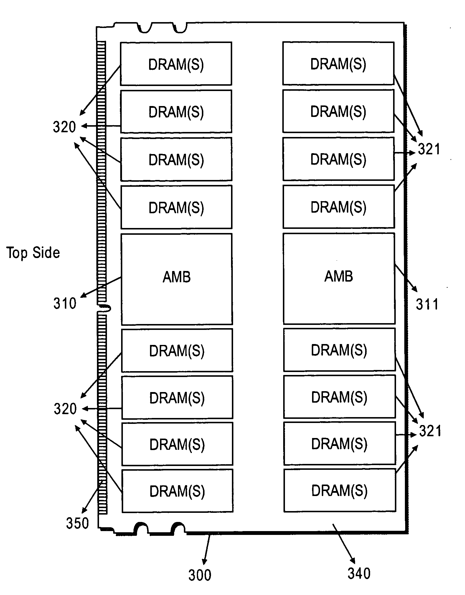
[0028]One or more embodiments of the present invention will now be described. FIG. 3a and FIG. 3b show a component mounting layout of an exemplary memory supermodule 300, including two Advanced Memory Buffer buffer devices 310 and 311, two sets of 18 DRAM memory devices 320 and 321, and a circuit board 340 carrying one single set of contact pads 350. The single set of contact pads is disposed in two rows: one on the top side of the supermodule, and one on the bottom side. FIG. 3a shows the top side of the supermodule; FIG. 3b shows the bottom side. Both AMBs 310 and AMB 311 are mounted to the same side of the circuit board 340. AMB 310 receives data from the DRAMs 320, and sends data and commands to the DRAMs 320. Similarly AMB 311 receives data from and sends commands and data to the DRAMs 321. AMB 310 and AMB 311 also communicate with each other, passing data and / or commands between themselves. The DRAMs 320 store the data received from and sent to their associated AMB. The circui...


PUM


Abstract

A memory supermodule containing two or more memory modules disposed on a common circuit board. Also, a memory supermodule comprising two or more memory modules, each module comprising a circuit board, the circuit boards connected by a flexible circuit. All modules in a supermodule share a single set of contact pads for establishing signal connection with a system in which the supermodule is used.

Description

CROSS-REFERENCE(S) TO RELATED APPLICATION(S)[0001]Not Applicable.STATEMENT AS TO RIGHTS TO INVENTIONS MADE UNDER FEDERALLY SPONSORED RESEARCH OR DEVELOPMENT[0002]Not Applicable.BACKGROUND OF THE INVENTION[0003]The present invention generally relates to integrated circuit assemblies, and in particular, to memory modules.[0004]Since the advent of electronic computers, computer makers have desired to put more computing power into smaller spaces. For example, computer makers want to minimize the amount of printed circuit board area they use. Alternatively, computer makers want to fit more circuitry into the prescribed dimensions of industry standard system boards.[0005]For use in computers, semiconductor memory is normally supplied in the form of pluggable modules. For a given amount of memory, computer makers want to minimize the board space used by the modules and their associated sockets. In some applications, however, module height is also a constraint. Thus it would be desirable to...

Claims


Application Information

Patent Timeline
IPC IPC(8): G11C5/02
CPCG11C5/04H05K2203/1572H05K2201/09409H05K1/181Y02P70/50
Inventor GULACHENSKI, ALAN MICHAELKOLLI, SATYADEVHELBERS, JAN HENDRIK
Owner SMART MODULAR TECH
Why Eureka
Try Eureka