
Method and System for Controlling a Receiver In a Digital Communication System

a digital communication system and receiver technology, applied in the field of signal processing in digital communication receivers, can solve the problems of poor detector performance, high threshold, and increased risk of signal miss detection, and achieve the effect of effective detector

Active Publication Date: 2008-01-03
STMICROELECTRONICS SRL +1
View PDF3 Cites 2 Cited by
  • Summary
  • Abstract
  • Description
  • Claims
  • Application Information

AI Technical Summary

Benefits of technology

[0019]Another object of this invention consists in proposing a control method for a receiver having to process a frame comprising a periodic sub-set, where it is not necessary any more to determine, as in known te

Problems solved by technology

Moreover, the threshold affects the performance of the detector and in particular the probability of a detection error, be it false alarm (FA)—i.e. the detection of a signal whereas there is only noise—or a miss detection (absence of signal detection).
If a threshold is set too low the first term of the above equation will increase—i.e. the probability of false alarm—and, if the threshold is set too high, then the other term will increase, thus increasing the risk of signal miss detection.
As a result, the detector's performance is poor.
Therefore, with known techniques one is confronted with the insurmountable problem of having to precisely determine the threshold K to use in a detector.
In practice, it is impossible to determine an optimal threshold because of the difficulty of knowing precisely the distribution laws and their characteristics in relation to the signal and noise in a concrete case.
The problem common to all these techniques lies in the importance of appropriately setting the value of threshold K.

Method used


Image

  • Method and System for Controlling a Receiver In a Digital Communication System
  • Method and System for Controlling a Receiver In a Digital Communication System
  • Method and System for Controlling a Receiver In a Digital Communication System

Examples


Embodiment Construction

[0047]The detection method according to the invention will now be described. The method is particularly adapted to realize a wireless communication technique such as the one known as 802.11. FIGS. 4 and 5 illustrate the structure of a frame comprising a short preamble (made up of periodic patterns B) and a long preamble (made up of patterns CP and C). Periodic pattern B makes it possible to carry out detection and estimation operations without using any other information (as can be obtained through a learning process).

[0048]Generally, a frame comprises a repetition of periodic elements B having a length of n symbols belonging to a given alphabet.

[0049]Let us consider a vector u (also represented by Uk in the figure) that corresponds to a group of periodic elements B and v (also represented by Uk+L in the figure), which is the element shifted by a whole number of periods. It should be noted that u and v can constitute any regrouping of a plurality of the periodic sub-sets noted as B ...


PUM


Abstract

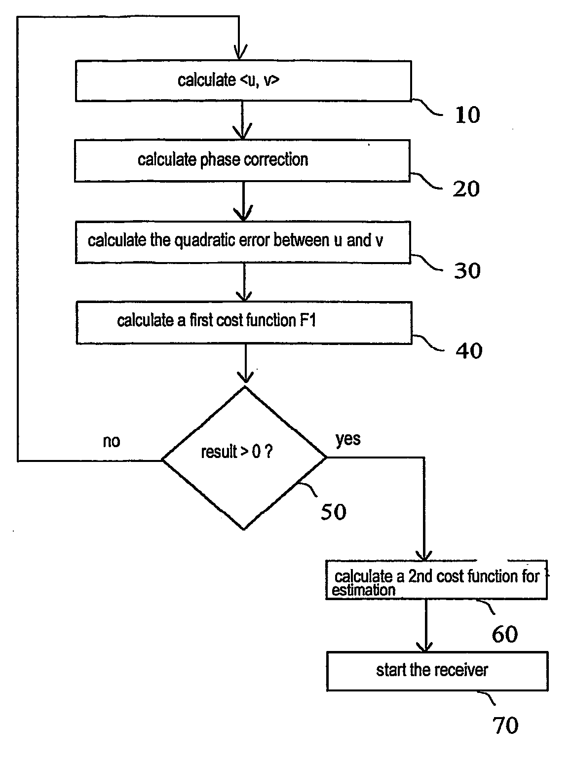
Detection method and device for a receiver in a digital communication system designed to process a frame comprising a periodic sub-set of length n, said method comprising the following steps: —determining a first vector u having a length n;—determining a second shifted vector v;—calculating a correlation function between said first and second vectors; —calculating a quadratic error function between said first and second vectors;—calculating a first cost function that is a linear combination of both preceding functions and, according to the sign of the result,—calculating a second cost function of frame beginning estimate; and—starting the communication system receiver.

Description

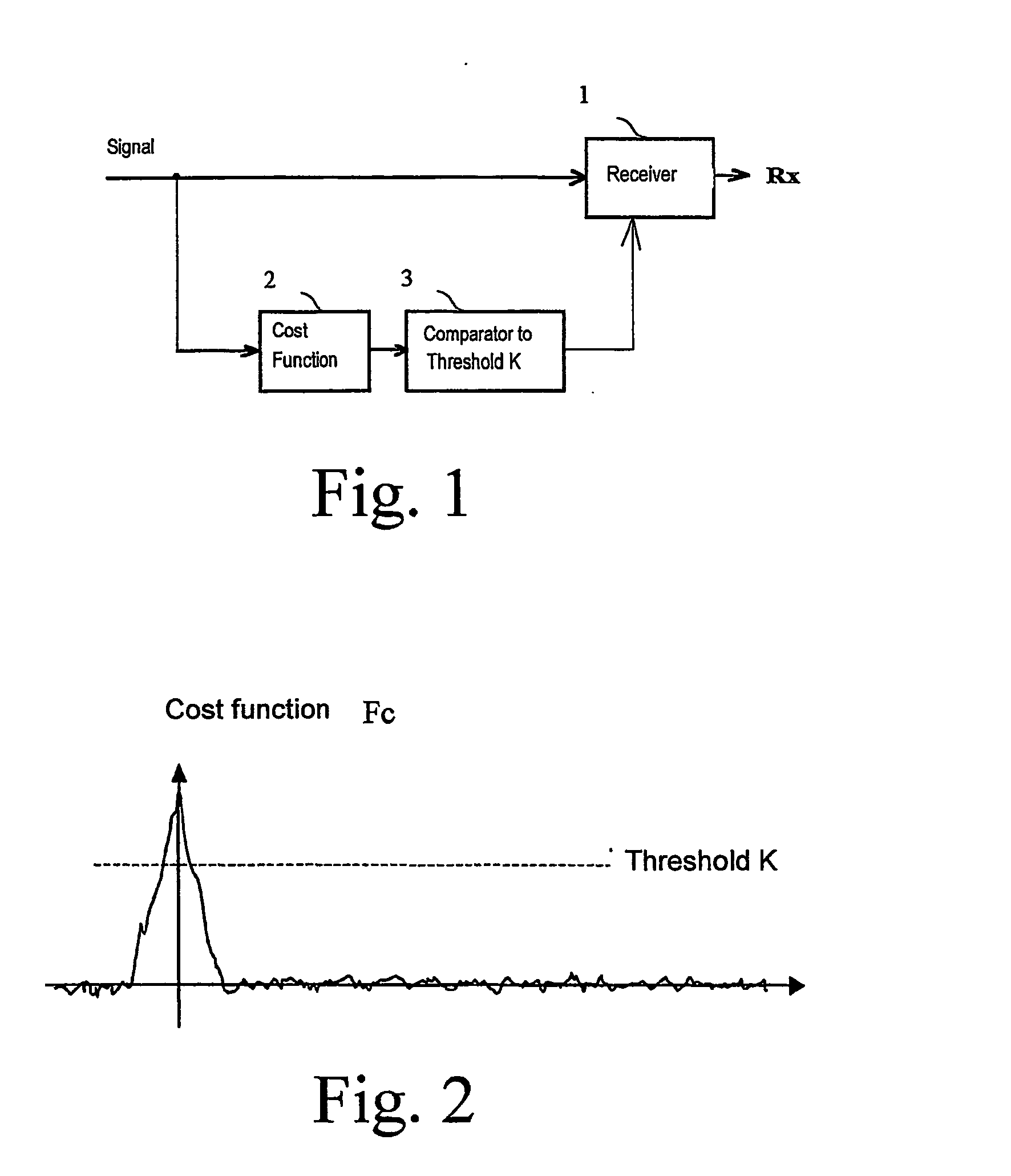
TECHNICAL FIELD OF THE INVENTION[0001]The present invention relates to signal processing in digital communication receivers in general, and more particularly to a method and a system for controlling a receiver in a digital communication system.BACKGROUND ART[0002]In any digital communication system, and in particular in wireless communication systems, the receiver is equipped, amongst other things, with a detection mechanism and a frame start time estimation mechanism.[0003]Detection is a well-known issue in the state of the art. It is an operation that consists in processing a signal received from a transmitter in order to determine if this signal is carrying useful information. Referring to FIG. 1, there is shown a receiver 1 receiving a signal that is also transmitted to a cost function F1 computation block 2. The result of the cost function is transmitted to a comparator 3 that compares this value with the value of a preset threshold K. The result of the comparison is then used,...

Claims


Application Information

Patent Timeline
IPC IPC(8): H04L7/04H04J3/06H04L27/26
CPCH04L27/2675H04L27/2656
Inventor LENEZ, THIERRYLENEZ, PATRICEPIERROT, JEAN-BENOITISSON, OLIVIER
Owner STMICROELECTRONICS SRL
Learn More