
User interface for color transfer control in textile processing equipment

Inactive Publication Date: 2008-01-03
IBM CORP
View PDF10 Cites 22 Cited by
  • Summary
  • Abstract
  • Description
  • Claims
  • Application Information

AI Technical Summary

Benefits of technology

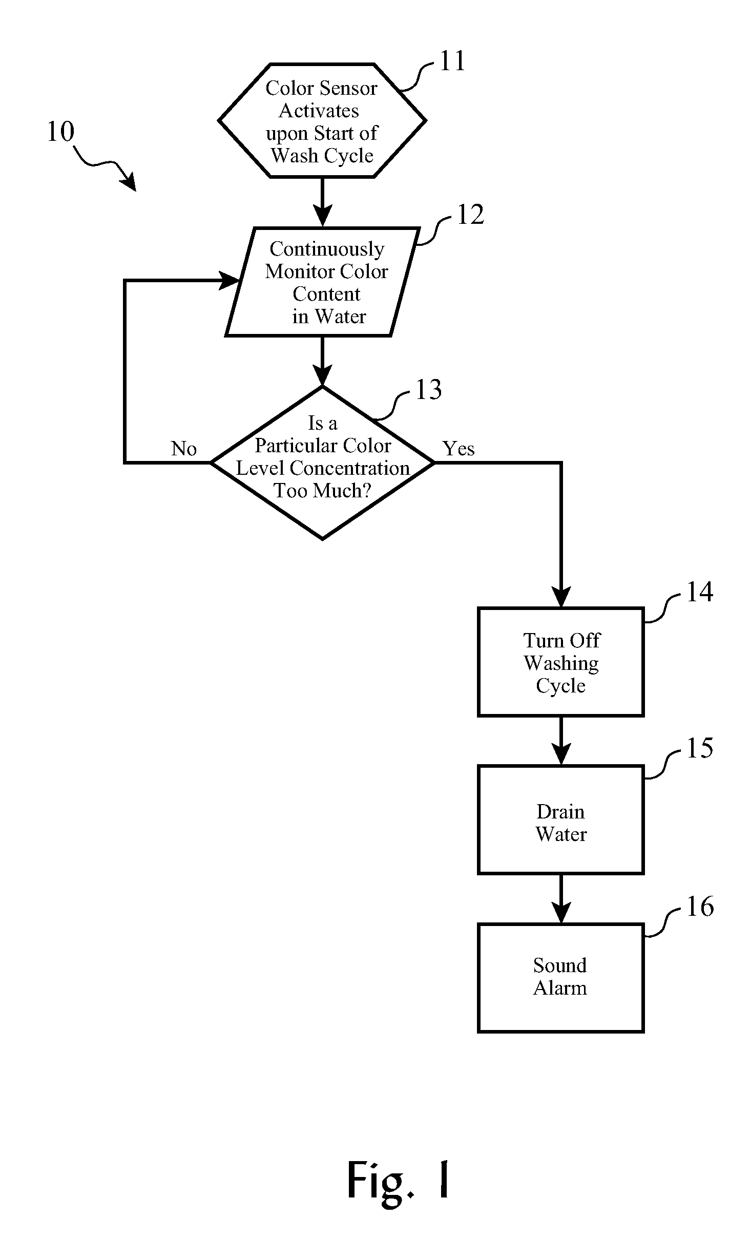
[0037]The inventors have realized that certain combinations of circuitry, automatic logic, and machine apparatus components may be employed according to the present invention to automatically detect color bleed in a wash load, and to automatically take abatement actions to reduce, stop, or minimize damage caused by color bleed.
[0043]The present invention provides an easy-to-use interface for a user to specify color bleed and color transfer operational parameters, using primary color components, such as red / green / blue, and using an easily configured actions menu.

Problems solved by technology

In some instances, bath temperature or detergent may intensify the color bleed problem.
However, these labels are often not followed, usually by mistake by including a new item inadvertently in a wash group, by forgetting to read the label, or other user error.
However, this adds to the cost of the articles, which can be an economic disadvantage to the retail sales of the item.
For some fabrics, pre-washing may increased the difficulty of handling the fabric during processing steps such as cutting, stitching, sewing, hemming, etc.
While this approach may partially abate color bleeding, it remains incomplete in its effect, as each sheet can only remove a finite amount of coloring substance from the bath, and each sheet can only remove coloring substance with which it comes in contact.
This still leaves many scenarios in which coloring substance may settle into articles, causing some amount of color bleed.
Further, this approach can be expensive, and is prone to error by the user (e.g. forgetting to drop a sheet in each wash load).

Method used


Image

  • User interface for color transfer control in textile processing equipment
  • User interface for color transfer control in textile processing equipment
  • User interface for color transfer control in textile processing equipment

Examples


based embodiments

Service-Based Embodiments

[0101]Alternative embodiments of the present invention include some or all of the foregoing logical processes and functions of the invention being provided by configuring software, deploying software, downloading software, distributing software, or remotely serving clients in an on-demand environment, to provide the logical control processes of the advanced washing machine.

[0102]Software Deployment Embodiment. According to one embodiment of the invention, the methods and processes of the invention are distributed or deployed as a service by a service provider to a client's computing system(s).

[0103]Turning to FIG. 3a, the deployment process begins (3000) by determining (3001) if there are any programs that will reside on a server or servers when the process software is executed. If this is the case then the servers that will contain the executables are identified (309). The process software for the server or servers is transferred directly to the servers sto...


PUM

PropertyMeasurementUnit
Threshold limitaaaaaaaaaa

Abstract

A system, method, and computer-readable medium encoded with software for allowing a user to configure controls of dye transfer in a dying machine or washing machine, including a user display having a user-operable selection device, a first dialog with primary color level indicators for setting a threshold to trigger a dye transfer control action, and threshold adjustment controls, and a second dialog having one or more control action enablers for enabling one or more control actions to be taken upon detection of a color reaching the threshold.

Description

CROSS-REFERENCE TO RELATED APPLICATIONS (CLAIMING BENEFIT UNDER 35 U.S.C. 120)[0001]This application is a continuation-in-part of U.S. patent application Ser. No. ______, filed ______ (to be amended when serial number and filing date have been assigned), docket number AUS920060020US1, which is commonly assigned with the present patent application.FEDERALLY SPONSORED RESEARCH AND DEVELOPMENT STATEMENT[0002]This invention was not developed in conjunction with any Federally sponsored contract.MICROFICHE APPENDIX[0003]Not applicable.INCORPORATION BY REFERENCE[0004]The related U.S. patent application Ser. No. ______, filed ______ (to be amended when serial number and filing date have been assigned), docket number AUS920060020US1, is incorporated by reference in its entirety.BACKGROUND OF THE INVENTION[0005]1. Field of the Invention[0006]This invention pertains to technologies for controlling machines and processes in which fabrics are washed, laundered, dyed, or otherwise treated in a li...

Claims


Application Information

Patent Timeline
IPC IPC(8): B32B27/12D06F34/22D06F34/30D06F34/32
CPCD06F35/006D06F39/005D06F39/004Y10T442/2508D06F34/22D06F34/32D06F2101/00D06F2105/60D06F2105/62D06F2105/08D06F2103/20D06F2105/02D06F34/30D06F2105/42
Inventor AGRAWAL, KAVITABODIN, WILLIAM K.POTLURI, LAKSHMI N.RYBCZYNSKI, GREGORY W.
Owner IBM CORP
Learn More