Surgical tool guide

a surgical and tool guide technology, applied in the field of surgical tool guides, can solve the problems of complicated workflow, associated risks of surgery, and difficulty in surgical navigation

Inactive Publication Date: 2008-01-03
GENERAL ELECTRIC CO
View PDF5 Cites 179 Cited by
  • Summary
  • Abstract
  • Description
  • Claims
  • Application Information

AI Technical Summary

Benefits of technology

[0010]Certain embodiments of the present invention provide a system for orienting a surgical tool with respect to a patient including: a tool guide for facilitating orientation of the surgical tool with respect to the patient, the tool guide including a mounting portion and a tool receiving portion, wherein the tool guide is capable of being integrated with at least a portion of an image intensifier subsystem including an adjustably moveable mounting structure.
[0011]Certain embodiments of the present invention provide a system for orienting a surgical tool with respect to a patient including: a tool guide for facilitating orientation of the surgical tool with respect to the patient, the tool guide including a mounting portion and a tool receiving portion, wherein the tool guide is capable of being integrated with at least a portion of a navigation subsystem including an adjustably moveable mounting structure.
[0012]Certain embodiments of the present invention provide a system for orienting a surgical tool with respect to a patient including: a tool guide for facilitating orientation of the surgical tool with respect to the patient, the tool guide including a mounting portion and a tool receiving portion, wherein the tool guide is capable of being integrated with at least a portion of an aiming subsystem including an adjustably moveable mounting structure.

Problems solved by technology

Surgery may have associated risks.
Surgical navigation may also complicate workflow, increase costs, and clutter a surgical environment, for example.
However, surgical robots may be relatively expensive, and may also take up the space in a potentially crowded surgical environment, for example.

Method used


Image

  • Surgical tool guide
  • Surgical tool guide
  • Surgical tool guide

Examples


Embodiment Construction

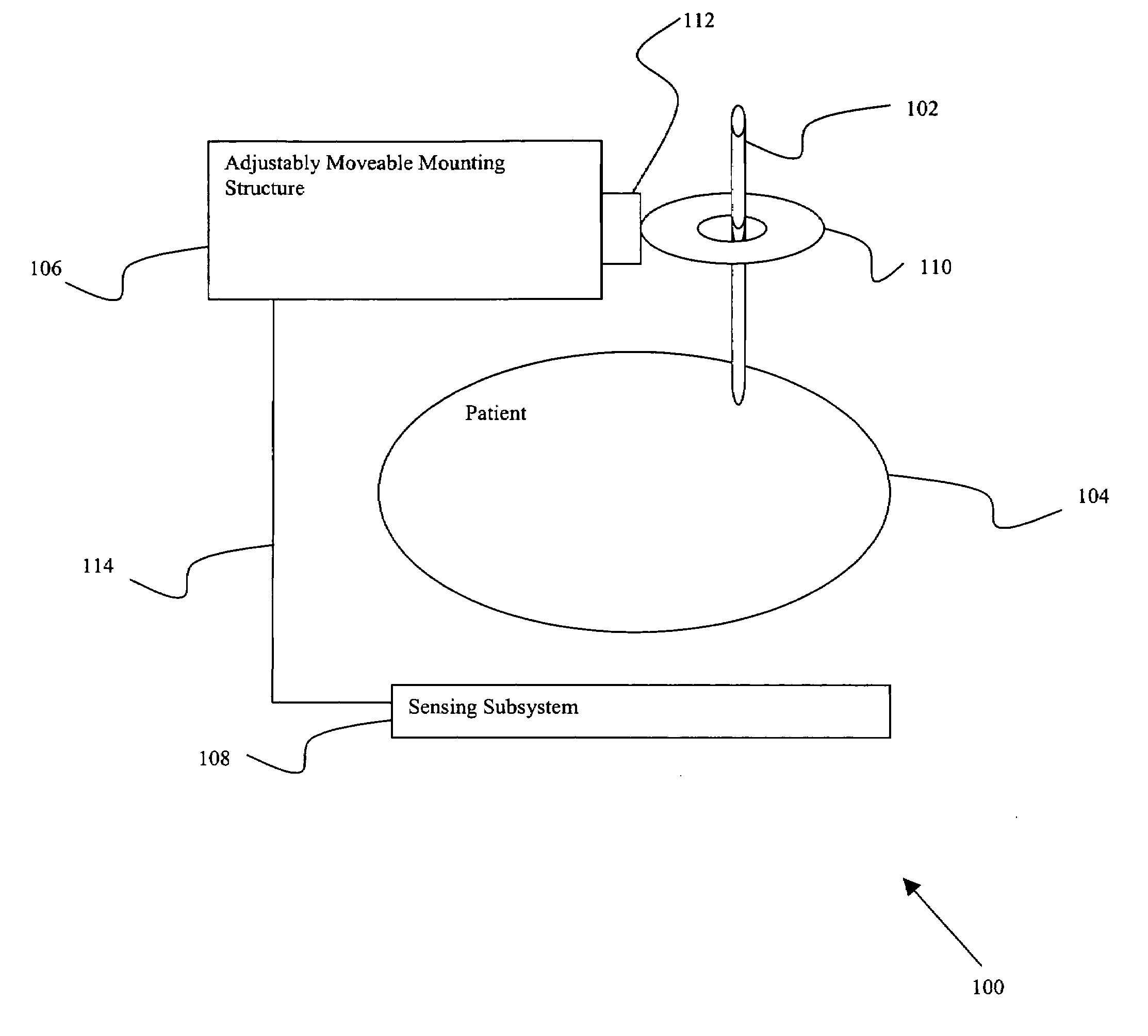
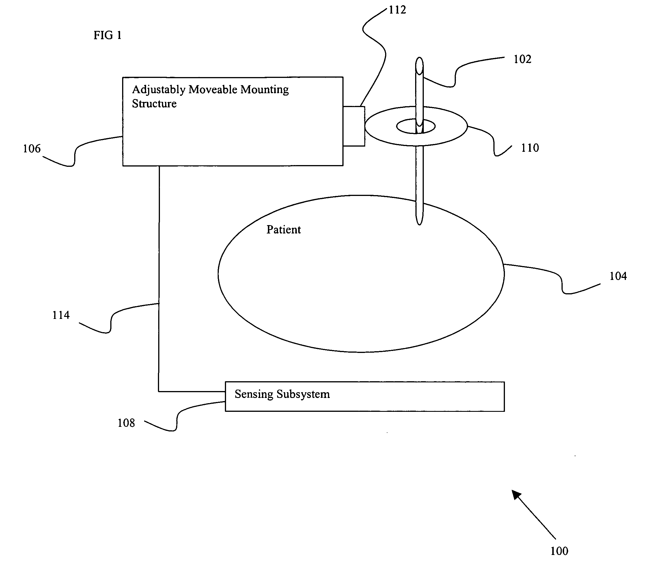
[0018]FIG. 1 shows a system 100 for orienting a surgical tool 102 with respect to a patient 104, in accordance with an embodiment of the present invention. The system 100 may include an adjustably moveable mounting structure 106 and a tool guide 110, for example. Optionally, the system 100 may also include a sensing subsystem 108, and / or an attachment mechanism 112, for example.

[0019]An adjustably moveable mounting structure 106 may be moveable in any of a number of directions and / or dimensions, such as linearly along one or more Cartesian axes (e.g. x, y, z), and / or radially, for example. The adjustably moveable mounting structure 106 may be moved to adjust the location (e.g. along a coordinate system), and / or may be moved to adjust the spatial orientation of the mounting structure (e.g. angulation of the structure 106 with respect to other objects of interest, such as the patient 104), for example. A position of the moveable structure 106 may include location and / or spatial orient...


PUM


Abstract

Certain embodiments of the present invention provide n system for orienting a surgical tool with respect to a patient including: a tool guide for facilitating orientation of the surgical tool with respect to the patient, the tool guide including a mounting portion and a tool receiving portion, wherein the tool guide is capable of being integrated with at least a portion of a radiological imaging subsystem including an adjustably moveable mounting structure. In an embodiment, the tool receiving portion is capable of receiving an end-effector. In an embodiment the at least a portion of the radiological imaging subsystem comprises a C-arm. In an embodiment the radiological imaging subsystem comprises a fluoroscopic imaging subsystem. In an embodiment, the end-effector comprises at least one of: an aperture, a cutting device, a drilling device, a clamp, a sleeve, a mounting surface, a ring, a rail, a threaded shaft, a clasp, a bayonet mount, an imaging device, an ultrasound probe, a surgical tool, a catheter, a pin, a screw, a plate, a drill, an awl, and a probe. In an embodiment, the tool guide further comprises an end-effector. In an embodiment, a position of the surgical tool is capable of being adjusted by automatically moving the adjustably movable mounting structure. In an embodiment, the system further comprises at least one position sensing subsystem for ascertaining a position of the surgical tool with respect to the patient.

Description

BACKGROUND OF THE INVENTION[0001]Embodiments of the present application relate generally to facilitating surgical procedures. Particularly, certain embodiments relate to providing systems, methods, and apparatuses for guiding a tool that may facilitate surgery.[0002]Surgery may have associated risks. It may, therefore, be desirable to both clinicians and patients to reduce both the magnitude and probability of any such surgical risks. One way to reduce risk may be to improve guidance of surgical tools.[0003]A C-arm may be used in radiological imaging subsystems, such as a fluoroscopic imaging system, for example. One trend in radiological imaging subsystems may involve improved positioning sub-systems. For example, in fluoroscopic imaging systems, recent developments have brought about improved precision motorized gantries, and a proliferation of tracking technology for surgical navigation.[0004]Surgical navigation may provide enhanced guidance and visualization, for example. For ex...

Claims


Application Information

Patent Timeline
Patent Type & Authority Applications(United States)
IPC IPC(8): A61B5/05
CPCA61B17/1703A61B19/201A61B19/2203A61B2019/5238A61B6/548A61B19/26A61B34/30A61B90/11A61B90/50A61B2090/376
Inventor JENSEN, VERNON THOMAS
Owner GENERAL ELECTRIC CO
Why Eureka
Try Eureka