Selecting electrode combinations for stimulation therapy

a stimulation therapy and electrode technology, applied in the field of electric stimulation therapy, can solve the problems of reducing the scope of search, reducing the amount of time a clinician spends, and requiring a great deal of trial and error

Active Publication Date: 2008-01-03
MEDTRONIC INC
View PDF21 Cites 91 Cited by
  • Summary
  • Abstract
  • Description
  • Claims
  • Application Information

AI Technical Summary

Benefits of technology

[0020] Identifying useful classes or groups of electrode combinations in accordance with the techniques described in the present disclosure prior to initiating other programming methodologies may help decrease the amount of time required to find one or more electrode combinations for programming into a medical device. Initially identifying the classes or groups of electrode combinations is a relatively time effective technique for identifying a useful electrode combination because the classes and groups of electrode combinations are representative of a broad range of therapeutic results that may be achieved by the many, and sometimes millions, of possible electrode combinations.
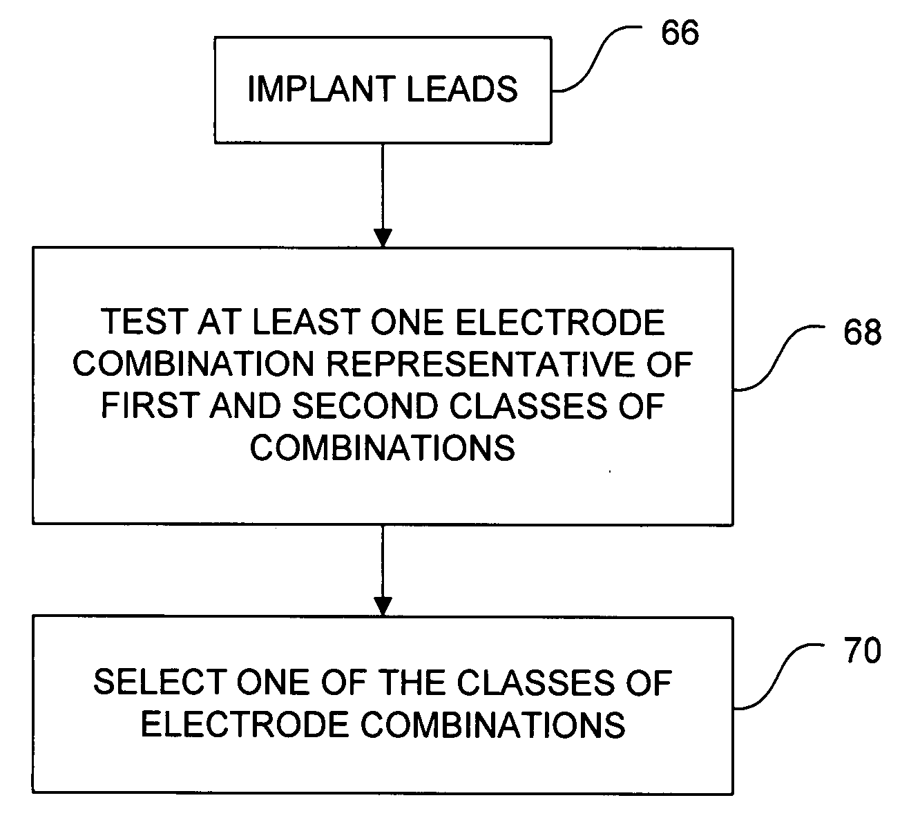
[0023] In some embodiments, a clinician and / or patient selects a best electrode combination, class or group based on testing electrode combinations from a library of combinations that includes a predetermined set of stored electrode combinations. In one embodiment, the stored combinations are representative of at least the first and second classes of combinations identified above (e.g., combinations utilizing one to two columns of electrodes, as well as combinations utilizing three columns of electrodes). In another embodiment, the stored combinations are representative of the five or more groups of combinations identified above. By selecting from a predetermined set of stored electrode combinations, embodiments of invention may allow the clinician or patient to identify the most effective class of electrode combinations, or in some embodiments, the most effective group of electrode combinations within the classes. By initially identifying a class of electrode combinations, the clinician or patient may be able to more quickly identify effective electrode combinations by testing combinations within the effective class (or group), rather than all possible combinations, after internalization of an implantable medical device.
[0026] Embodiments of the invention may provide advantages. For example, electrode combinations within different classes or groups may result in different stimulation fields. Accordingly, testing at least one representative combination from each class and / or group may help decrease the amount a clinician may invest to select an effective electrode combination for a patient. The effect of the different stimulation fields may be characterized by a plurality of therapy (or “efficacy”) metrics such as, but not limited to, the extent to which dorsal column fibers are stimulated, the ratio of dorsal column fiber stimulation to dorsal root stimulation, or the depth of tissue stimulated, which may be similar within a class, but different between classes. The therapy metrics may also help decrease the amount of time a clinician spends selecting an effective electrode combination. In some cases, the clinician may express a desired program in terms of clinically relevant therapy metrics.
[0027] Due to the anatomical and symptom differences between patients, one class of electrode combinations may be more effective for one patient than the other patients. Alternatively, one group of combinations from within the classes may be more effective than the other groups. Some embodiments of the invention may allow a clinician or the patient to identify the effective class, while other embodiments of the invention may allow the clinician or patient to identify the effective group. This identification may reduce the scope of a search for electrode combinations, and may also allow a more informed determination of what lead configuration, e.g., the number of leads or columns and rows of electrodes, to implant within the patient.

Problems solved by technology

The process of selecting values for the parameters that provide adequate results can be time consuming, and may require a great deal of trial and error before a “best” program is discovered.
As a portion of the overall parameter selection process, the process of selecting electrodes and the polarities of the electrodes, e.g., the process of selecting electrode combinations, can be particularly time-consuming and tedious.
The lengthy trial and error process of selecting electrode combinations occurs not only prior to implanting the implantable medical device and leads, but may also occur periodically for the life of the therapy.
For example, the lengthy trial and error process of selecting electrode combinations occurs only after implanting the implantable medical device and leads.

Method used


Image

  • Selecting electrode combinations for stimulation therapy
  • Selecting electrode combinations for stimulation therapy
  • Selecting electrode combinations for stimulation therapy

Examples


example 1

COMPUTER MODELING EXAMPLE 1

[0180] Data relating to a plurality of electrode combinations was obtained using computer modeling of lower thoracic placement of electrodes using a first computer modeling technique. The data was for the electrode combinations that included electrodes within less than three columns (i.e., a combination from the first class), at least one transverse electrode combination, and at least one longitudinal electrode combination (i.e., combinations from the second class). In the first model, a McIntyre-Richardson-Grill myelinated fiber model was used, in which the medial dorsal column fiber is about 12.8 μm (31 nodes) with a 5.7 μm collateral (10 nodes) and the dorsal root fiber is about 15 μm (8 nodes) and attaches to the 12.8 μm (31 nodes) longitudinal fiber in the lateral dorsal column.

[0181] Three columns of electrodes were modeled, where the electrodes were arranged in a 4-8-4 arrangement. A low thoracic spinal cord model utilized in the first computer mod...

example 2

COMPUTER MODELING EXAMPLE 2

[0186] A second computer modeling technique included calculating the direct effects of electrical stimulation of the spinal cord using various electrode combinations and geometries using a second computer model, the University of Twente Model. The spinal cord stimulation (SCS) computer model basically consists of a volume conductor model of the spinal cord and its surroundings, and an electrical model of the myelinated nerve fibers in the spinal cord.

[0187] Descriptions of the SCS computer model and of the methods applied in this report are described in a number of previously published papers, including: How do geometric factors influence epidural spinal cord stimulation? J. Holsheimer, J. J. Struijk, Stereotactic and Functional Neurosurgery, vol. 56, pp. 234-249, 1991, Effects of electrode geometry and combination on nerve fiber selectivity in spinal cord stimulation, J. Holsheimer, J. J. Struijk, N. Tas, Medical & Biological Engineering & Computing, vol...

example 3

COMPUTER MODELING EXAMPLE 3

[0194] In a third computer modeling example, a plurality of electrode combinations from each of the two classes were modeled for two different cerebral spinal fluid (CSF) depths. A first depth of 3.8 mm represents a lower thoracic region of the spine and a second depth of 2.4 mm represents a cervical region of the spine. The electrode combinations that were tested are shown in FIG. 17A, and given the alphabetic designators A, B, C, D, E, and F. The third computer model suggested that guarded cathode electrode combinations (B-F) provide a lower recruitment ratio compared to unguarded bipolar electrode combination (A). Thus, if a clinician is interested in achieving a lower recruitment ratio, either electrode combination B from the first class or electrode combinations C-F may be selected as trial electrode combinations for further testing. A “trial electrode combination” does not necessarily indicate that the electrode combination is tested during a trialin...


PUM


Abstract

Techniques for selecting electrode combinations for stimulation therapy are described. The techniques include selecting one or more electrode combinations based on information associating a plurality of electrode combinations with at least one value of a therapy metric. The therapy metric comprises a quantifiable result of delivery of stimulation, and may be generated computer modeling of delivery of stimulation via the electrode combinations. In one embodiment, a clinician may deliver stimulation via a baseline electrode combination, receive patient feedback to the baseline electrode combination, select a therapy metric based on the patient feedback, and select additional electrode combinations based on the selected therapy metric and the information associating the electrode combinations with therapy metric values. In another embodiment, the clinician may select a therapy metric prior to providing a test stimulation and select additional electrode combinations based on the selected therapy metric and the information associating electrode combinations with metric values.

Description

[0001] This application claims the benefit of U.S. Provisional Application No. 60 / 817,735, filed Jun. 30, 2006, and U.S. Provisional Application No. 60 / 873,220, filed Dec. 6, 2006. The entire content of U.S. Provisional Application Nos. 60 / 817,735 and 60 / 873,220 is incorporated herein by reference.TECHNICAL FIELD [0002] The present invention relates to electrical stimulation therapy. More particularly, the present invention relates to techniques for selecting combinations of implanted electrodes for delivery of stimulation to a patient. BACKGROUND [0003] Implantable medical devices may be used to deliver electrical stimulation therapy to patients to treat a variety of symptoms or conditions such as chronic pain, tremor, Parkinson's disease, epilepsy, urinary or fecal incontinence, or gastroparesis. An implantable medical device may deliver electrical stimulation therapy via leads that include electrodes located proximate to the spinal cord, pelvic nerves, stomach, or within the brai...

Claims


Application Information

Patent Timeline
Patent Type & Authority Applications(United States)
IPC IPC(8): A61N1/05G16H20/40
CPCA61N1/0529A61N1/0534A61N1/0553G06F19/3481A61N1/37247G06F19/3406A61N1/36185G16H40/63G16H20/40
Inventor KING, GARY W.GOETZ, STEVEN M.TIDEMAND, KEVIN K.WESSELINK, WILBERT A.MIYAZAWA, GABRIELA C.GREENBERG, JORDAN J.
Owner MEDTRONIC INC
Why Eureka
Try Eureka