Femoral head resurfacing

a femoral head and resurfacing technology, applied in the field of femoral head resurfacing, can solve the problems of adversely affecting the goal of satisfactorily restoring, affecting the performance of these implants, and affecting the fixation of components, etc., to achieve the effect of surface replacemen

Inactive Publication Date: 2008-01-03
HOWMEDICA OSTEONICS CORP
View PDF99 Cites 16 Cited by
  • Summary
  • Abstract
  • Description
  • Claims
  • Application Information

AI Technical Summary

Benefits of technology

[0017]It is an object of the present invention to provide a more successful surface replacement of the femoral portion of a total hip replacement by improvements to a stemless, modular approach to femoral hip resurfacing.
[0019]It is another aspect of the invention to provide ball and sleeve components with altered geometries to allow variation in the orientation of the ball component with respect to the axis defined by the femoral head and neck and to provide a system of location features to facilitate adjusting the ball component orientation during surgery.
[0020]In the preferred embodiment the internal bore of the sleeve component is inwardly tapered. Thus, the taper can be co-axial with the femoral neck although there may be advantages in orienting the axis of the taper slightly more vertical when in position so that it is closer to the average force vector acting on the femoral head during human activity. With this tapered sleeve the interface between the sleeve and the prepared bone is placed in compression to aid in retention and facilitate bone ingrowth. The sleeve bore may be arranged with anti rotation features such as ridges which extend along the length of the sleeve to engage the prepared bone surface and prevent rotation of the sleeve relative to the bone.

Problems solved by technology

The satisfactory performance of these implants can be affected not only by the design of the component itself, but also by the surgical positioning of the implanted component and the long-term fixation of the implant.
Improper placement or positioning of the implant can adversely affect the goal of satisfactorily restoring the clinical bio-mechanics of the joint as well as impairing adequate fixation of the component when implanted.
This is especially important since installation of an orthopedic implant often involves an extensive and difficult medical procedure, and therefore replacement or revision of the installed implant is typically difficult and traumatic.
These stem type prostheses are very successful but when they fail the stem can create considerable damage inside the bone.
The implant can move about inside the bone causing the intramedullary cavity to be damaged.
Because a stiff stem transmits the forces more directly into the femoral shaft, such implants have the further disadvantage that they can weaken the surrounding bone proximal to the hip joint due to stress shielding.
While this method of fixation by cement provides immediate fixation and resistance to the forces encountered, and allows the surgeon to effectively position the device before the cement sets, it is not without problems.
Over time, the mechanical properties and the adhesive properties of the bone cement degrade; eventually the forces overcome the cement and cause the components to become loose due to a failure at the cement / bone or cement / stem interface.
A shortfall of this approach is that, in contrast to components that utilize cement fixation, surfaces designed for biological ingrowth do not provide for immediate fixation because it takes time for the bone to grow into the specially prepared surface.
Prior art designs often require the entire implant to be replaced even if only a portion of the implant fails.
This is often due to the implant suffering from a decrease in support from the adjacent bone from stress shielding or other negative effects of the implant on surrounding bone.
Small movement of the device against the bone caused friction of the bone and the bending loads on the peg often caused them to break out underneath the bony femoral neck.
These latter double cup designs commonly failed either by a crack progressing around the bone cement between the prosthetic femoral shell and the bone or by a fracture of the bone across from one side of the prosthetic femoral component rim to the other.

Method used


Image

  • Femoral head resurfacing
  • Femoral head resurfacing
  • Femoral head resurfacing

Examples


Embodiment Construction

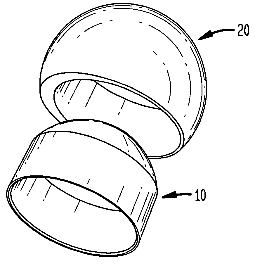
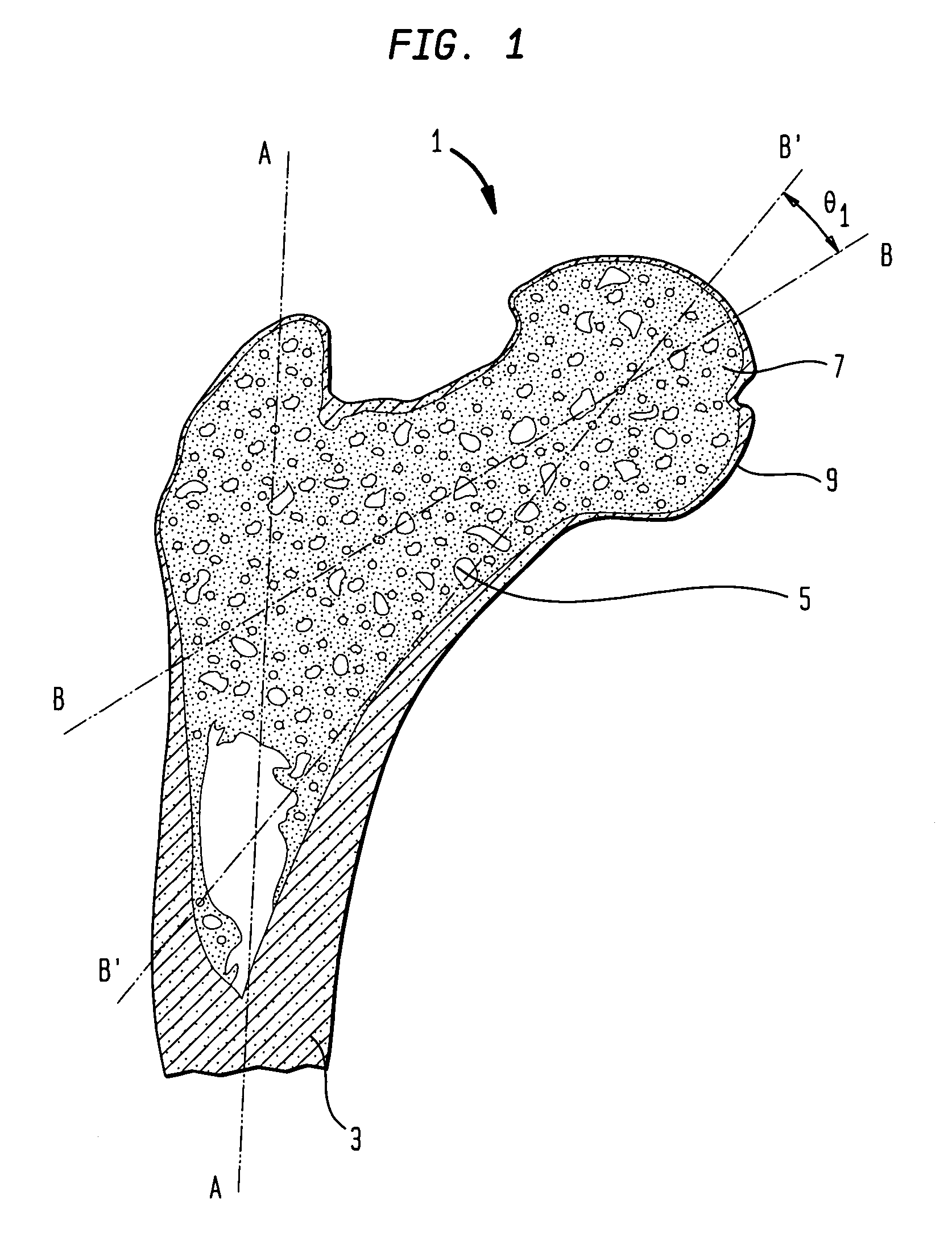
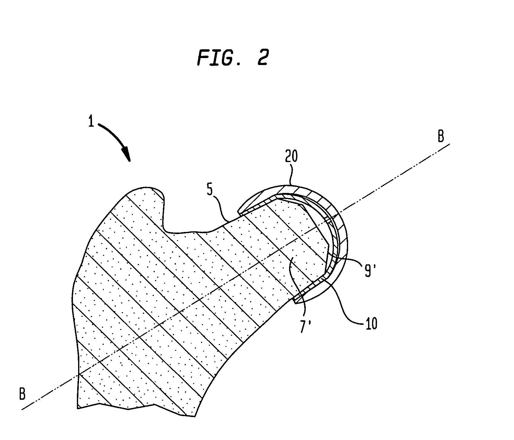
[0040]As shown in FIG. 2, a proximal femur as depicted in FIG. 1 has been surgically prepared for the implantation of a femoral hip resurfacing prosthesis. The preparation consists of a re-shaping of the femoral head 7, in this instance, as a surface of revolution about the femoral neck axis B-B. The femoral head 7 has been re-shaped by known surgical techniques as a prepared femoral head 7′, such that the femoral head surface 9 has been removed, creating a prepared femoral head surface 9′. Arranged in close contact with the prepared femoral head surface 9′, is a sleeve 10. In turn, a ball component 20 is fitted over the sleeve 10. In this manner, a modular prosthesis comprising the sleeve and ball is emplaced on the prepared femoral head with various embodiments and advantages as will be further described.

[0041]FIG. 3 depicts a top view of the prosthesis of FIG. 2 fitted on a prepared femoral head. The projection of the femoral shaft axis A-A, depicted in FIG. 1, is shown on the up...


PUM

PropertyMeasurementUnit
porosityaaaaaaaaaa
porosityaaaaaaaaaa
diametersaaaaaaaaaa

Abstract

A hip resurfacing femoral prosthesis has a partial ball component having an outer surface shaped to conform to an acetabular socket and has a mating sleeve component with an internal bore adapted to receive a femoral head. The head has been shaped and dimensioned to engage the bore and is retained by bone ingrowth, an interference fit or by bone cement. The ball component and sleeve axes may be offset to reposition the outer surface.

Description

BACKGROUND OF THE INVENTION[0001]The present invention relates generally to systems, kits and methods for joint replacement using multiple components. In one embodiment, the present invention includes as components a ball component and a sleeve component for adapting the ball component to a prepared femoral head.[0002]Artificial joint prostheses are widely used today, restoring joint mobility to patients affected by a variety of conditions, including degeneration of the joint and bone structure. Typically, the failed bone structure is replaced with an orthopedic implant that mimics, as closely as possible, the structure of the natural bone and performs its functions. The satisfactory performance of these implants can be affected not only by the design of the component itself, but also by the surgical positioning of the implanted component and the long-term fixation of the implant. Improper placement or positioning of the implant can adversely affect the goal of satisfactorily restor...

Claims


Application Information

Patent Timeline
Patent Type & Authority Applications(United States)
IPC IPC(8): A61F2/36
CPCA61B2017/00902A61F2310/00976A61F2/3603A61F2/4637A61F2/4684A61F2002/30011A61F2002/3009A61F2002/30219A61F2002/30332A61F2002/30345A61F2002/30347A61F2002/30367A61F2002/30403A61F2002/30538A61F2002/30542A61F2002/3055A61F2002/30553A61F2002/30616A61F2002/30617A61F2002/30714A61F2002/30738A61F2002/30795A61F2002/30934A61F2002/3605A61F2002/4631A61F2220/0025A61F2220/0033A61F2230/0067A61F2250/0006A61F2250/0008A61F2250/0023A61F2250/0064A61F2250/0089A61F2250/0091A61F2250/0097A61F2310/00017A61F2310/00023A61F2310/00029A61F2310/00095A61F2310/00131A61F2310/00179A61F2310/00592A61F2310/00796A61F2310/0097A61F2/30767A61F2002/30217A61F2002/3054A61F2002/3071
Inventor LEDGER, ROBERT E.TULKIS, PETERWANG, AIGUOSERVIDIO, DAMON
Owner HOWMEDICA OSTEONICS CORP
Why Eureka
Try Eureka