Magnetic pushpin

a pushpin and magnetic technology, applied in the field of pushpins, can solve the problems of permanent hole, painful injury to hands, feet or other areas of an unwary person, and difficulty in removing such devices from the support surface afterward, and achieve the effect of adding structural and operating advantages

a pushpin and magnetic technology, applied in the field of pushpins, can solve the problems of permanent hole, painful injury to hands, feet or other areas of an unwary person, and difficulty in removing such devices from the support surface afterward, and achieve the effect of adding structural and operating advantages

US20080005873A1Inactive Publication Date: 2008-01-10HELEN OF TROY LIMITED

Image

  • Magnetic pushpin
  • Magnetic pushpin
  • Magnetic pushpin

Examples


Embodiment Construction

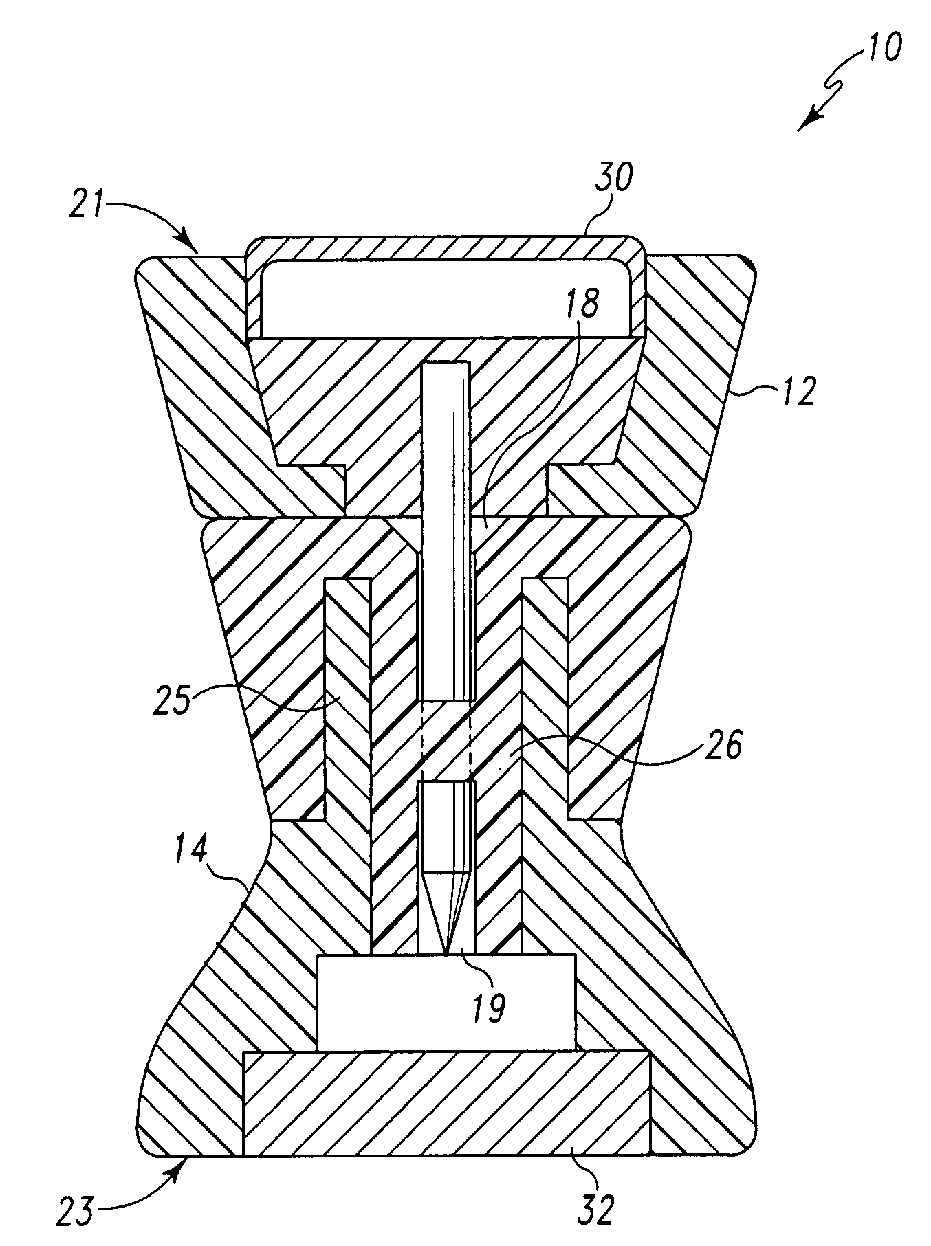
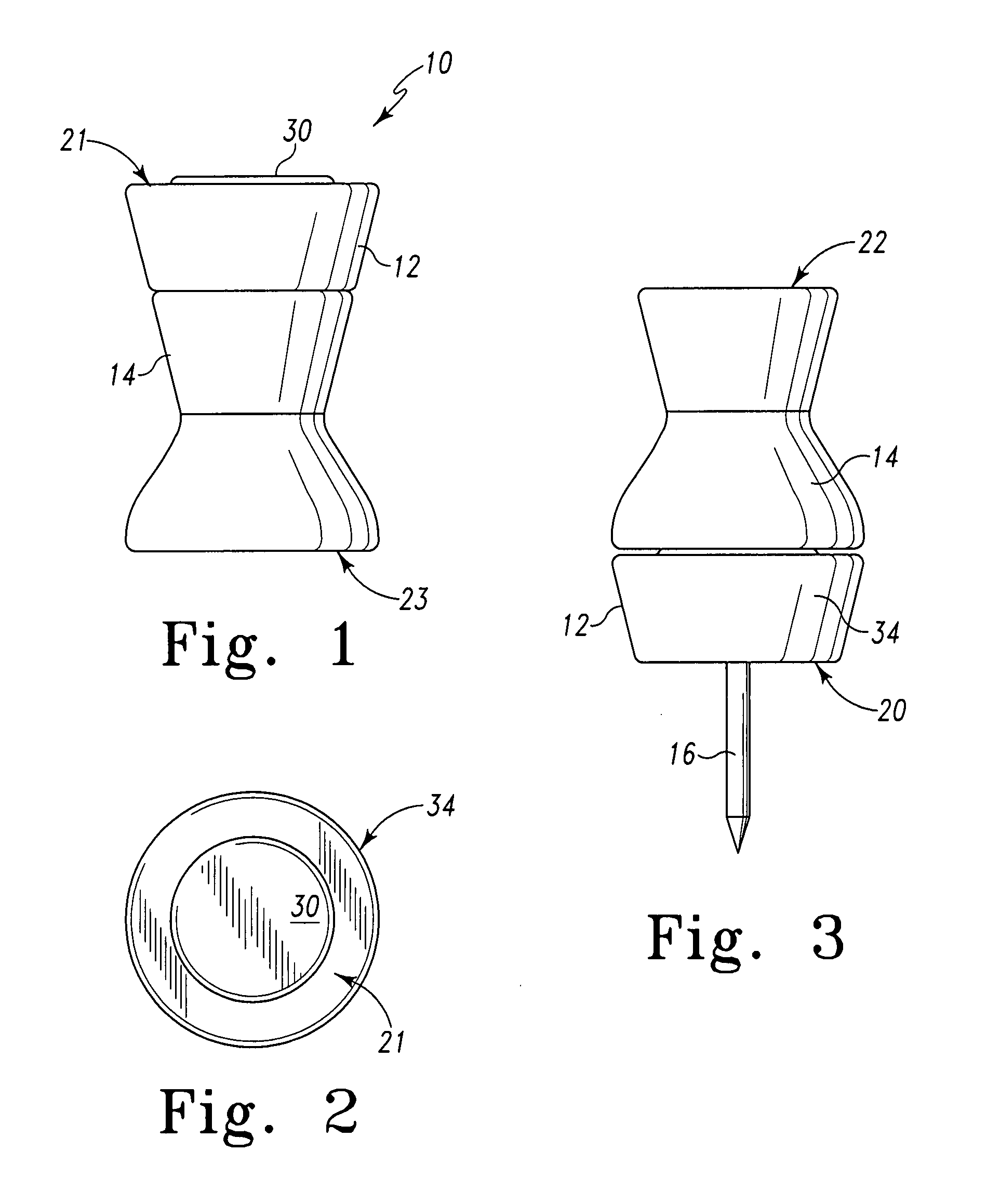
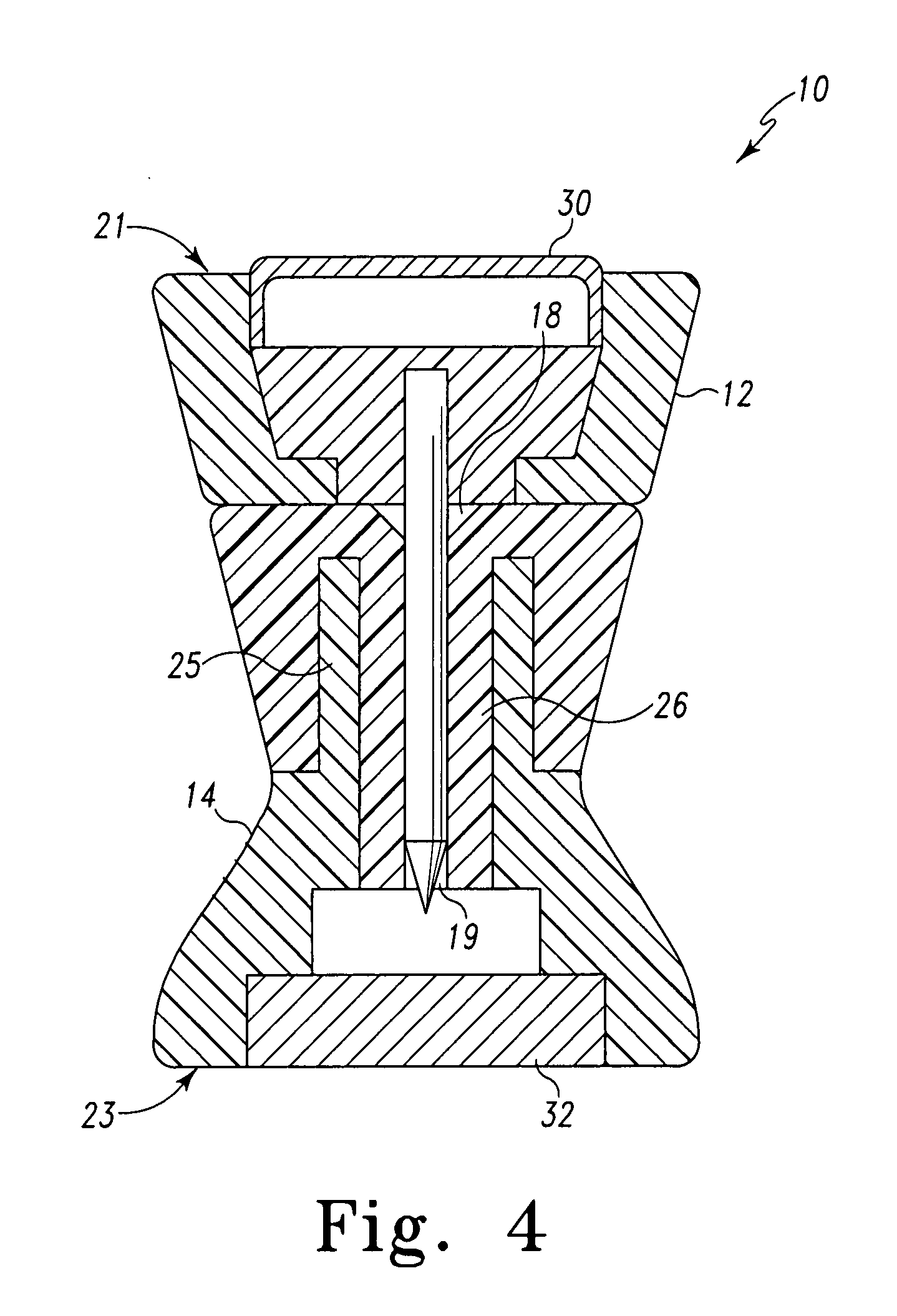
[0018]While this invention is susceptible of embodiments in many different forms, there is shown in the drawings and will herein be described in detail a preferred embodiment of the invention with the understanding that the present disclosure is to be considered as an exemplification of the principles of the invention and is not intended to limit the broad aspect of the invention to embodiments illustrated.

[0019]For purposes of the present application, the following are definitions should be applied for each of the listed terms and phrases, or variations thereof:

[0020]“Magnetically susceptible” refers to a material, for example iron or steel, which has the ability to be attracted by a magnet.

[0021]“Magnetic” refers to a component which is capable of attracting iron, steel, or a magnetically susceptible material.

[0022]“Magnetically connected” or “magnetically connectable” refers to a component which is held or is capable of being held in a position by the attractive forces of a magne...


PUM


Abstract

A pushpin which is readily adaptable for use as a pushpin or a magnet is disclosed. The pushpin includes a first body having opposing surfaces, a pin member extending from the body, and a magnetically susceptible component positioned opposite the pin member on the body. The pushpin also includes a second body having opposing surfaces, an opening, a cavity beginning at the opening and extending into the second body, and a magnetically susceptible component positioned on the second body. The particular pushpin cavity is configured to conceal the pin and at least one of either the magnetically susceptible component on the first body and the magnetically susceptible component on the second body is magnetic. Retention means for retaining the pin when it is inserted into the cavity are also provided within the cavity and include friction applied to the pin by a cavity wall. Lining at least a portion of the cavity with a thermoplastic rubber (TPR) material, or providing a plug of such or similar material within the cavity for piercing by the pin, provides such friction.

Description

RELATED APPLICATION[0001]In accordance with 35 U.S.C. 120, this application claims the earlier filing benefit of U.S. Provisional Application Ser. No. 60 / 818,937, filed on Jul. 6, 2006, the disclosure of which is hereby incorporated by reference.TECHNICAL FIELD OF THE INVENTION[0002]The present device relates to pushpins used to secure material such as photos, papers, and the like to a vertical surface. Particularly, the present device relates to magnetic pushpins having multiple uses.BACKGROUND OF THE INVENTION[0003]Pushpins, or thumbtacks as they are more commonly known, are used to secure articles such as drawings, photos, cards, notes and other such documents on a support surface such as a wall, ceiling or a bulletin board. Conventional pushpins have a head and a pin projecting outwardly from the head. The pin has a tip for insertion through the article and into the support surface.[0004]A drawback of these conventional pushpins is the damage that can be caused when the pin pier...

Claims


Application Information

Patent Timeline
10 Jan 2008
Publication
US20080005873A1
IPC
A44B21/00; A44B99/00
CPC
Y10T24/32; B43M15/00
Inventors
BARTON, PRISCILLA; VERNON, RYAN