Random-period chip transfer method

a chip transfer and random period technology, applied in the direction of electric programme control, program control, instruments, etc., can solve the problems of troublesome replacement of cams, failure to follow irregular changes of pitch, and difficulty in replacing cams, so as to improve the productivity and quality of ic cards or rf tags

Inactive Publication Date: 2008-01-10
HALLYS CORP
View PDF7 Cites 49 Cited by
  • Summary
  • Abstract
  • Description
  • Claims
  • Application Information

AI Technical Summary

Benefits of technology

[0009] Accordingly, the object of the present invention is to provide a random-period chip transfer apparatus that can realize accurate positioning and high-speed transfer, and that can also respond to changes of the speeds and pitches at which chips and works are fed.

Problems solved by technology

If the periodic motion of the transfer heads is rigidly fixed, following problems may occur for the mass production mentioned above.
That is, it is necessary to replace the cam troublesomely for every products of a different size or pitch.
Besides, because the motion of the transfer heads is limited, the heads cannot follow an irregular change of the pitch of fed parts or an irregular change of the pitch of moving works.
Those transfer heads cannot respond to random pitch changes or real-time fine adjustment, and consequently, accurate parts positioning is impossible.
However, the single transfer head is not adaptable for high-speed mass production even though it may ensure positioning accuracy.

Method used


Image

  • Random-period chip transfer method
  • Random-period chip transfer method
  • Random-period chip transfer method

Examples


Embodiment Construction

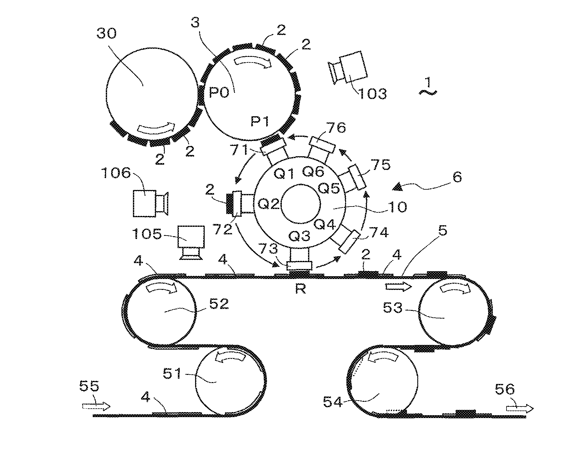
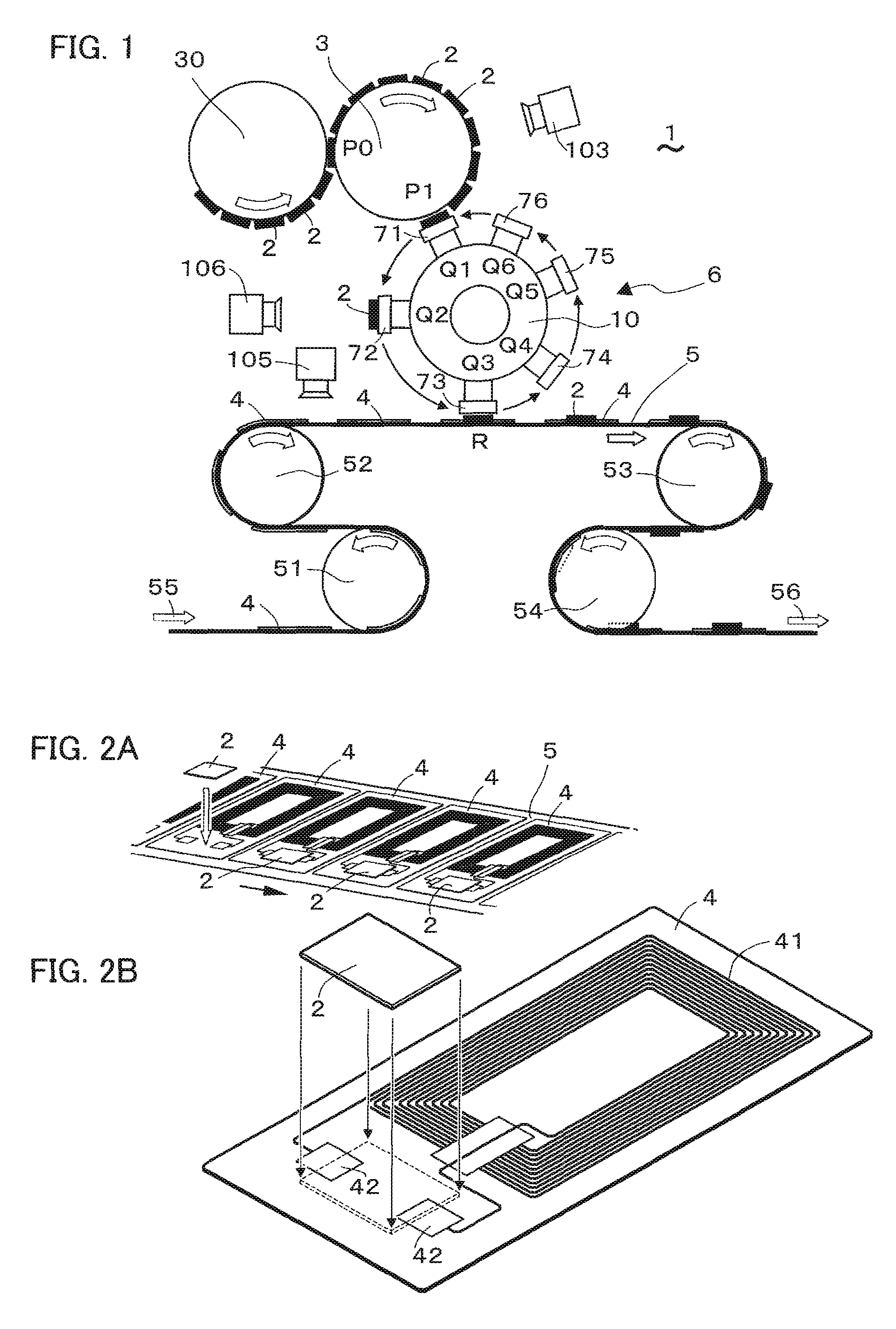
[0033]FIG. 1 shows a chip transfer apparatus 1 embodying the present invention. The transfer apparatus 1 includes a first carrier 3, a second carrier 5 and two transfer engines 6. The first carrier 3 carries chips 2 on it and feeds the carried chips. The second carrier 5 carries works 4, onto which chips 2 can be transferred. Each transfer engine 6 includes three coaxial revolvers 10. The coaxial revolvers 10 of the two transfer engines 6 revolve coaxially with each other around a horizontal axis CL (FIG. 6B). Each coaxial revolver 10 of one of the engines 6 is fitted with an end-effector 71, 73 or 75. Each coaxial revolver 10 of the other engine 6 is fitted with an end-effector 72, 74 or 76. Each of the end-effectors 71-76 receives a chip 2 from the first carrier 3 and transfers the received chip onto a work 4 on the second carrier 5.

[0034] The end-effectors 71-76 are arranged at intervals in a circle coaxial with the horizontal axis CL (FIG. 6B). While the end-effectors 71-76 are...


PUM

PropertyMeasurementUnit
speedaaaaaaaaaa
speedsaaaaaaaaaa
revolving speedaaaaaaaaaa

Abstract

A chip transfer apparatus includes a first carrier for feeding chips and a second carrier for carrying works on it. The transfer apparatus also includes a transfer engine including two or more coaxial revolvers, which can revolve coaxially with each other. Each of the coaxial revolvers includes an end-effector for receiving a chip from the first carrier and transferring the received chip onto a work on the second carrier. The end-effectors of the coaxial revolvers are arranged in a circle coaxial with the revolvers. The end-effectors sequentially receive chips from the first carrier at substantially zero speed relative to the first carrier and transfer the received chips onto works on the second carrier at substantially zero speed relative to the second carrier. While the end-effectors are revolving, they undergo periodic speed change control for timing adjustment and speed adjustment for the chip reception and transfer.

Description

CROSS-REFERENCES TO RELATED APPLICATIONS [0001] This is a divisional of U.S. patent application Ser. No. 10 / 677,180, filed with the United States Patent Office on Oct. 2, 2003, subsequently published Aug. 24, 2004, as U.S. Pre-grant Patent Application Publication No. 2004 / 0154161 A1, and claims the benefit of priority of Japanese Patent Application No. 2003-31165, filed with the Japan Patent Office on Feb. 2, 2003, subsequently registered Jan. 25, 2006, as Japanese Patent No. 3,739,752 B2.BACKGROUND OF THE INVENTION [0002] 1. Field of the Invention [0003] The present invention relates to a transfer apparatus for transferring parts onto works with revolving end-effectors. [0004] 2. Description of the Related Art [0005] Conventionally, there has been such an electronic parts mounting apparatus available in the field of semiconductor production for receiving chips, transferring the received chips onto works and arranging, sticking or electrically connecting the transferred chips on the...

Claims


Application Information

Patent Timeline
Patent Type & Authority Applications(United States)
IPC IPC(8): B23P19/00H05K3/30H05K13/04G06K19/077H01L21/00H05K13/00H05K13/02H05K13/08
CPCB65G29/00Y10T29/4913G06K19/07718G06K19/07749G06K19/0775H01L21/67132H01L21/67144H05K13/02Y10T29/53178Y10T29/53039Y10T29/49004Y10T29/53191Y10T29/5313Y10T29/53174B65G47/848B65H2701/1914B65B15/04
Inventor AOYAMA, HIROSHINISHIGAWA, RYOICHI
Owner HALLYS CORP
Why Eureka
Try Eureka