Concrete conduit members

a conduit and concrete technology, applied in the field of fittings, can solve the problems of inability to use the fittings with pouring forms of different sizes, the cost of the fittings themselves and the cost of shipping the fittings, and achieve the effect of reducing the size of the shipping container used

Active Publication Date: 2008-01-10
HIGH CONCRETE GROUP
View PDF26 Cites 6 Cited by
  • Summary
  • Abstract
  • Description
  • Claims
  • Application Information

AI Technical Summary

Benefits of technology

[0008]An advantage of the present invention is that the end connector permits interchangeable use with differently sized concrete pouring molds.
[0009]A further advantage of the present invention is that the end connectors can be used in combination with inexpensive materials that connect to the end connectors.
[0010]A still further advantage of the present invention is that the end connectors are nestable with each other to reduce the size of shipping containers used in transporting connectors.

Problems solved by technology

There are disadvantages associated with the use of these prefabricated fittings.
One disadvantage is the inability to use the fittings with pouring forms of different size.
Other disadvantages are costs; both the costs of the fittings themselves and the costs associated with shipping the fittings, since the fittings are typically large and cumbersome.

Method used


Image

  • Concrete conduit members
  • Concrete conduit members
  • Concrete conduit members

Examples


Embodiment Construction

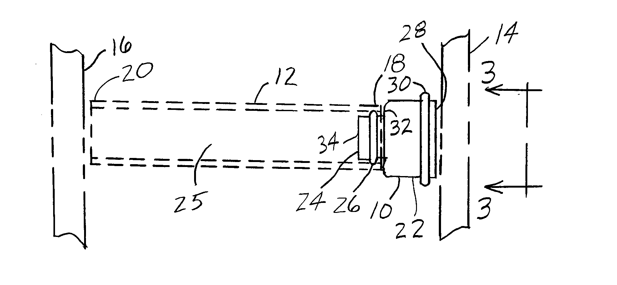
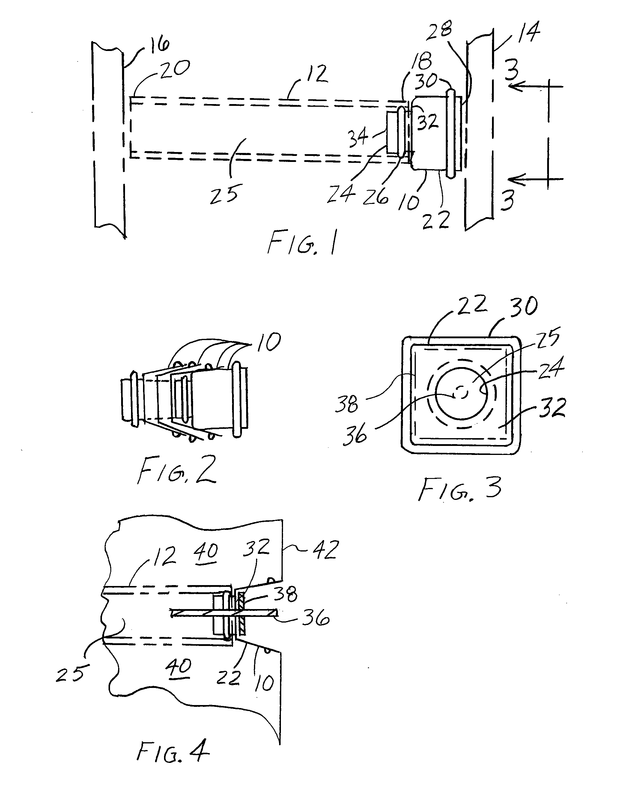
[0035]The present invention is directed to an end connector 10 depicted in FIGS. 1-4. End connector 10 includes a body 22 having opposite ends 28, 32 that is preferably structurally enhanced by a surface feature 30, such as an annular rib, which is disposed between ends 28, 32. Extending from end 32 is a sleeve 24 that terminates at an end 34, which sleeve 24 having a surface feature 26 disposed between ends 32, 34. A tube 12 having ends 18, 20 is assembled with end connector 10 by directing end 34 of sleeve 24 inside end 18 of tube 12 until end 18 abuts or is adjacent to end 32 of body 22. Surface feature 26 closely conforms with the inside surface of tube 12, providing a substantially fluid tight connection that prevents infiltration of concrete latents, such as concrete paste (e.g., fine cement, water, sand), slag or pazzolans into body 22 and tube 12. In one arrangement, after assembly, tube 12 and end connector 10 are disposed in a pouring form having opposed walls 14, 16 so th...


PUM

PropertyMeasurementUnit
surface featureaaaaaaaaaa
thicknessaaaaaaaaaa
sizeaaaaaaaaaa

Abstract

An end connector for use in forming a conduit in a poured concrete member is provided. The end connector is adapted to be secured to a wall of a concrete member pouring form, the end connector having a surface feature to achieve a substantially fluid tight seal upon receiving an end of a tube that extends between opposite walls of the pouring form to form a conduit in the poured structural member. The end connector has a geometry capable of nesting with at least one other end connector to minimize a container size required to transport the end connectors.

Description

FIELD OF THE INVENTION[0001]The present invention is directed to fittings for use in forming conduits in moldable building materials, and more specifically to fittings for use in forming conduits in concrete structures.BACKGROUND OF THE INVENTION[0002]Fittings have been used in concrete structural members, such as structural tees, panels, and connections between girders and columns to help assemble or reinforce the structural members together. Additionally, such fittings can provide convenient access for routing non-structural components, such as electrical wiring or plumbing. These fittings are placed in the concrete pouring forms prior to pouring the concrete, displacing concrete that is poured in the concrete forms to provide the desired passageways in the resulting concrete structural members.[0003]Typically, the fittings have been of unitary construction. That is, the fittings are prefabricated to fit one specific pouring form for use in producing identical concrete members. Th...

Claims


Application Information

Patent Timeline
Patent Type & Authority Applications(United States)
IPC IPC(8): E04C3/30
CPCB28B23/0043H02G3/28E04G15/061
Inventor BAUR, KENNETH C.ALLAMENA, ALICIAGRAZIANO, GARY C.
Owner HIGH CONCRETE GROUP
Why Eureka
Try Eureka