Pulse detonation engines and components thereof

Inactive Publication Date: 2008-01-10
GENERAL ELECTRIC CO
View PDF4 Cites 17 Cited by
  • Summary
  • Abstract
  • Description
  • Claims
  • Application Information

AI Technical Summary

Benefits of technology

[0011] One embodiment of a transition piece for a pulse detonation engine comprises a body ...

Problems solved by technology

One main challenge in developing pulse detonation engines having a pulse detonation combustor (PDC) is understandin...

Method used


Image

  • Pulse detonation engines and components thereof
  • Pulse detonation engines and components thereof
  • Pulse detonation engines and components thereof

Examples


Embodiment Construction

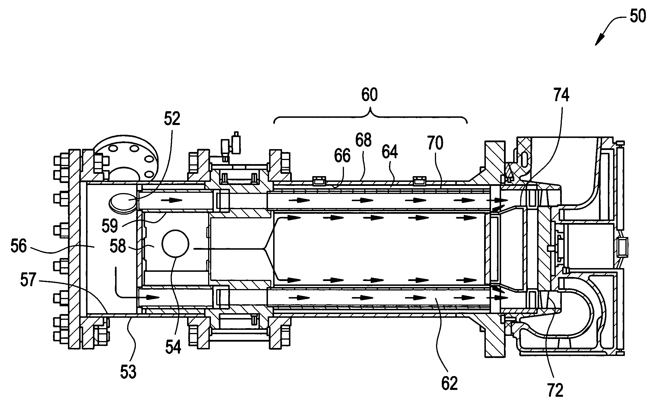
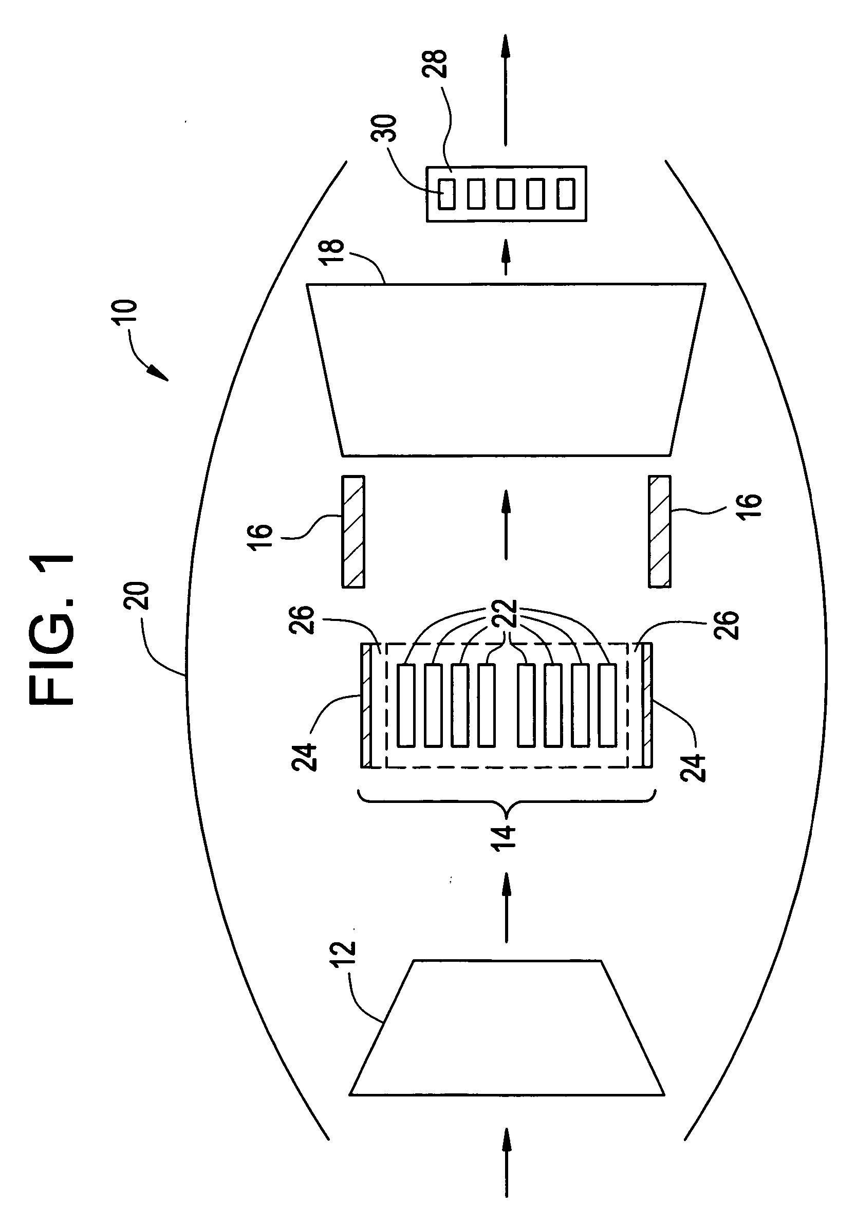
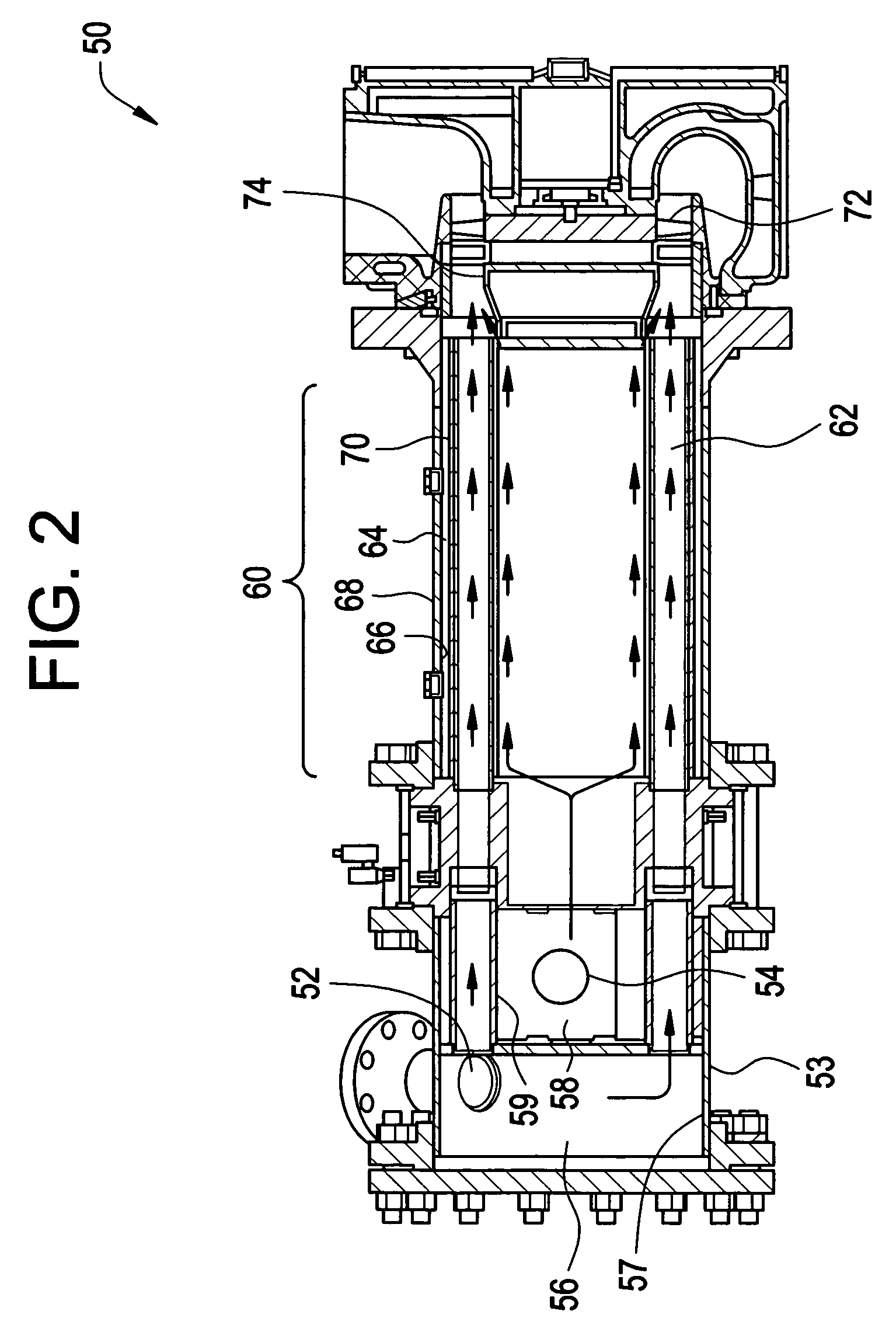
[0018] Disclosed herein are pulse detonation engines and components of the pulse detonation engine. As will be discussed in greater detail, the pulse detonation engine generally comprises a pulse detonation combustor located within a coaxial liner that allows the pulse detonation combustor to be cooled; a transition piece located downstream of the pulse detonation combustor configured to direct flow from the combustor and coaxial liner to an axial turbine assembly located downstream; and the axial turbine assembly. A source of a compressed oxidizer, e.g., a compressor, is located upstream of the pulse detonation combustor.

[0019] In the descriptions that follow, the term “axial” refers broadly to a direction parallel to the axis about which the rotating components of the gas turbine engine rotate. An “upstream” direction refers to the direction from which the local flow is coming, while a “downstream” direction refers to the direction in which the local flow is traveling. In the mos...


PUM


Abstract

A pulse detonation engine comprises a primary air inlet; a primary air plenum located in fluid communication with the primary air inlet; a secondary air inlet; a secondary air plenum located in fluid communication with the secondary air inlet, wherein the secondary air plenum is substantially isolated from the primary air plenum; a pulse detonation combustor comprising a pulse detonation chamber, wherein the pulse detonation chamber is located downstream of and in fluid communication with the primary air plenum; a coaxial liner surrounding the pulse detonation combustor defining a cooling plenum, wherein the cooling plenum is in fluid communication with the secondary air plenum; an axial turbine assembly located downstream of and in fluid communication with the pulse detonation combustor and the cooling plenum; and a housing encasing the primary air plenum, the secondary air plenum, the pulse detonation combustor, the coaxial liner, and the axial turbine assembly.

Description

STATEMENT REGARDING FEDERALLY SPONSORED RESEARCH OR DEVELOPMENT [0001] This invention was made with U.S. government support under Government Contract No.: 2167851001 awarded by the National Aeronautics and Space Administration (NASA). The U.S. government has certain rights in this invention.BACKGROUND [0002] The present disclosure generally relates to turbine engines, and more particularly, to pulse detonation engines. [0003] A conventional gas turbine engine generally includes a compressor and turbine arranged on a rotating shaft(s), and a combustion section between the compressor and turbine. The combustion section burns a mixture of compressed air and liquid and / or gaseous fuel to generate a high-energy combustion gas stream that drives the rotating turbine. The turbine rotationally drives the compressor and provides output power. Industrial gas turbines are often used to provide output power to drive an electrical generator or motor. Other types of gas turbines may be used as ai...

Claims


Application Information

Patent Timeline
IPC IPC(8): F23R7/00
CPCF23C15/00Y02T50/675F23R7/00F23R3/005Y02T50/60
Inventor TANGIRALA, VENKAT ESWARLURASHEED, ADAMVANDERVORT, CHRISTIAN LEEDEAN, ANTHONY JOHN
Owner GENERAL ELECTRIC CO
Why Eureka
Try Eureka