Ratchet tool

a ratchet and tool technology, applied in the direction of wrenches, friction clutches, clutches, etc., can solve the problems of improper design of the locating structure for changing the work direction and is also vulnerable to damage, and achieve the effect of precise locating operation and better withstanding normal tear and wear

Inactive Publication Date: 2008-01-10
HU CHENG TSAN
View PDF2 Cites 6 Cited by
  • Summary
  • Abstract
  • Description
  • Claims
  • Application Information

AI Technical Summary

Benefits of technology

[0006]The primary purpose of the present invention is to provide a ratchet tool that allows to change work direction of a tooling sleeve by turning a dialer to either side to cause its retaining block to drive the post of either pawl to disengage the pawl from the teeth of the tooling sleeve to solve the problems of improper design of direction changing and comparatively shorter service life found with the prior art.
[0009]Wherein the stopper pushes against an opening end of the bore by means of a third elastic member; the locking bolt is secured in place by means of a rivet or alternatively by means of a bolt and a nut; the dialing handle of the dialer is further disposed with a plurality of locating recesses corresponding to the stopper of the handle. The number of the locating recesses on the dialing handle of dialer may be of three or two. Accordingly, the present invention provides the advantages of precise locating operation in changing work direction and better withstanding normal tear and wear.

Problems solved by technology

As taught in U.S. Pat. No. 5,875,693, a hand ratchet tool operates on a gear to engage for locating; however, its locating structure for changing work direction is not properly designed and is also vulnerable to damage.

Method used


Image

  • Ratchet tool
  • Ratchet tool
  • Ratchet tool

Examples


embodiments

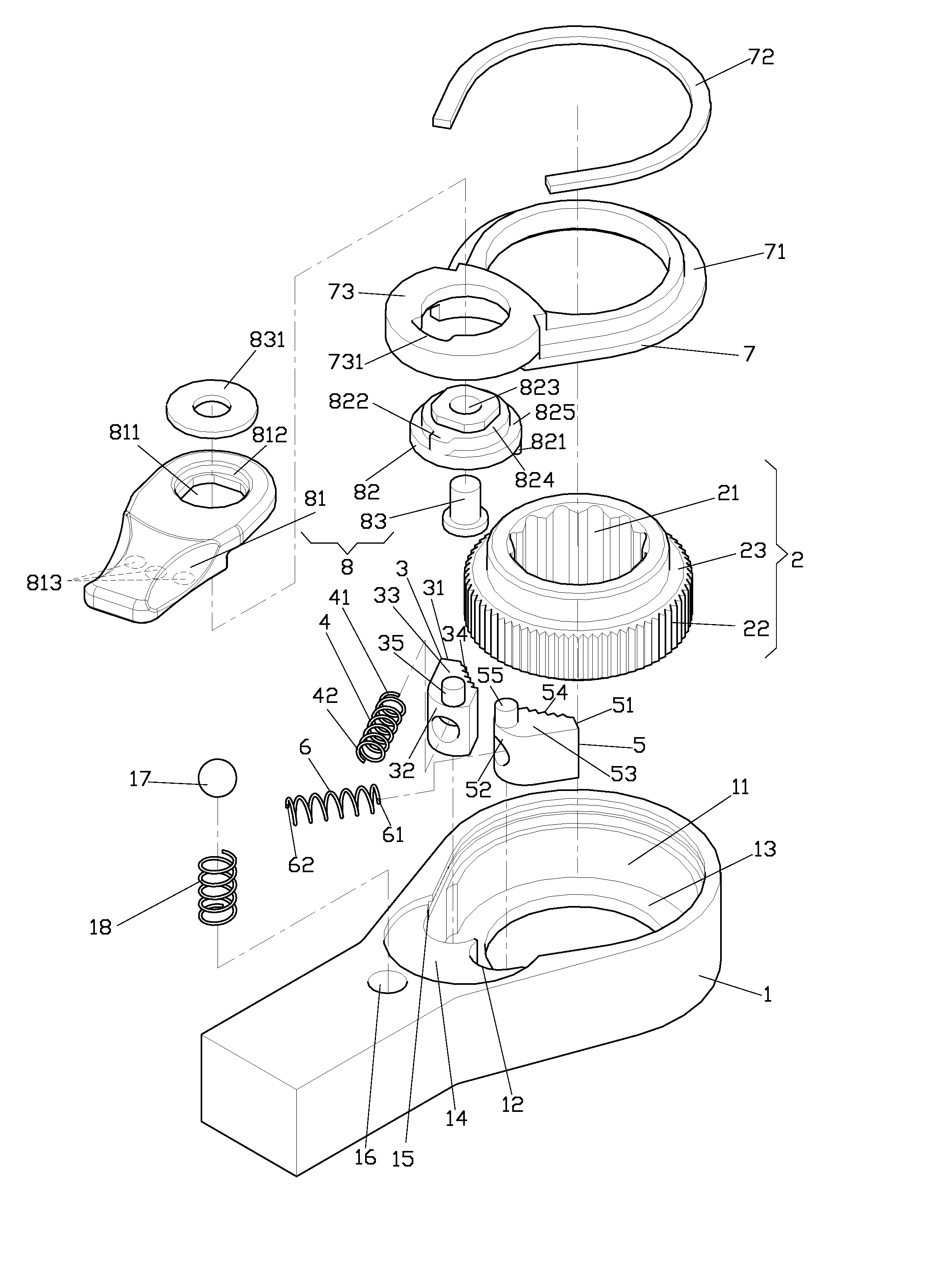
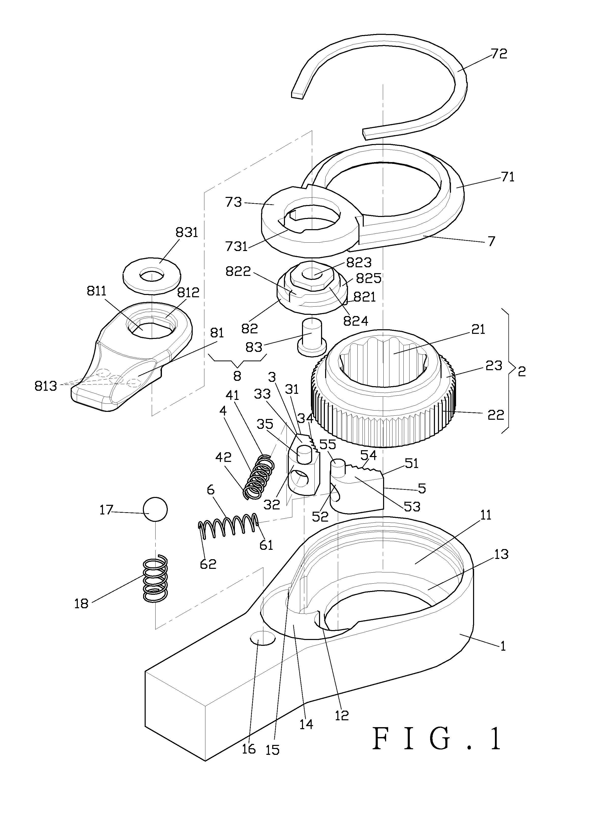
[0015]Referring to FIGS. 1 and 2, a preferred embodiment of the present invention comprises a handle (1), a tooling sleeve (2), a first pawl (3), a first elastic member (4), a second pawl (5), a second elastic member (6), a retaining ring (7), and a dialer (8).

[0016]The handle (1) comprises a chamber (11) and a pair of recesses (12). The recesses (12) are adjacent to the chamber (11). The tooling sleeve (2) received in the chamber (11) of the handle (1) comprises an insertion hole (21), and the outer circumference of the tooling sleeve (2) is disposed with teeth (22). The first pawl (3) is contained in one of the recesses (12) of the handle (1). The first pawl (3) comprises teeth (34) corresponding to the teeth (22) of the tooling sleeve (2) and a first post (35). The first elastic member (4) holds against the first pawl (3) and the recess (12) containing the first pawl (3). The second pawl (5) is contained in the other of the recesses (12) of the handle (1). The second pawl (5) com...


PUM


Abstract

A ratchet tool includes a handle, a tooling sleeve, a first pawl, a first elastic member, a second pawl, a second elastic member, a retaining ring, and a dialer. The outer circumference of the tooling sleeve received in the handle is disposed with teeth. The pawls and the elastic members are contained in the handle. Each of the pawls is disposed with teeth and a post. The retaining ring covers up the pawls and the elastic members and is secured to the handle. The dialer is pivoted to the retaining ring to change work direction of the tooling sleeve by moving the pawls as driven by the posts linked to the dialer when the dialer is turned to either side.

Description

CROSS-REFERENCE TO RELATED APPLICATIONS[0001]This application is a continuation-in-part of my application filed Jul. 5, 2006, Ser. No. 11 / 428,773, which is incorporated herein by reference in its entirety.BACKGROUND OF THE INVENTION[0002](a) Field of the Invention[0003]The present invention relates to a ratchet tool, and more particularly to one that allows change work direction of a tooling sleeve by turning a dialer to either side to cause its retaining block to drive the post of either pawl thus to disengage the pawl from the teeth of tooling sleeve.[0004](b) Description of the Prior Art[0005]There are many types of ratchet tools generally available in the market with each giving own characteristics. As taught in U.S. Pat. No. 5,875,693, a hand ratchet tool operates on a gear to engage for locating; however, its locating structure for changing work direction is not properly designed and is also vulnerable to damage.SUMMARY OF THE INVENTION[0006]The primary purpose of the present ...

Claims


Application Information

Patent Timeline
Patent Type & Authority Applications(United States)
IPC IPC(8): B25B13/46
CPCB25B13/463
Inventor CHEN, CHIU-TANG
Owner HU CHENG TSAN
Why Eureka
Try Eureka