Suspension Apparatus

a suspension and suspension technology, applied in mechanical devices, transportation and packaging, bicycle equipment, etc., can solve the problems of significant technical and cost challenges, increase the weight, etc., and achieve the effects of improving the control of the wheel camber, increasing the deflection stiffness, and reducing the weigh

Inactive Publication Date: 2008-01-10
TRW LIMITED
View PDF17 Cites 44 Cited by
  • Summary
  • Abstract
  • Description
  • Claims
  • Application Information

AI Technical Summary

Benefits of technology

The patent describes a new design for a vehicle suspension system that allows for better control of wheel camber under suspension deflections. This is achieved by adding a stabilizer bar that connects the second fixing region (the load) to the first fixing region (the support). The stabilizer bar is made of composite material and does not require any moving parts. The design also includes supplementary torsion control links to fully control the camber of the wheels under deflection of the arm. These links, known as radius arms, can be made of composite and attached to the stub axle carrier on the Smart Arm with rotation capability. The arm can then deflect as required for vertical suspension movement, with the radius arms free to control the rotation of the stub axle from the vertical and hence control the camber of the wheel. The design provides significant weight, space, and cost advantages over a conventional suspension assembly, while still retaining its active capacity. Additionally, a reinforcing sleeve can be added to provide support function to the arm.

Problems solved by technology

The technical problem addressed in this patent is the need for a simpler and lighter suspension system for vehicles that can control movement in a predefined manner, without being heavy, prone to corrosion, wear, and presenting significant technical and cost challenges in development of active suspension capabilities. This requires suspension "adaptivity" that occurs in "real time" on the vehicle to control its behavior in use.

Method used


Image

  • Suspension Apparatus
  • Suspension Apparatus
  • Suspension Apparatus

Examples


Embodiment Construction

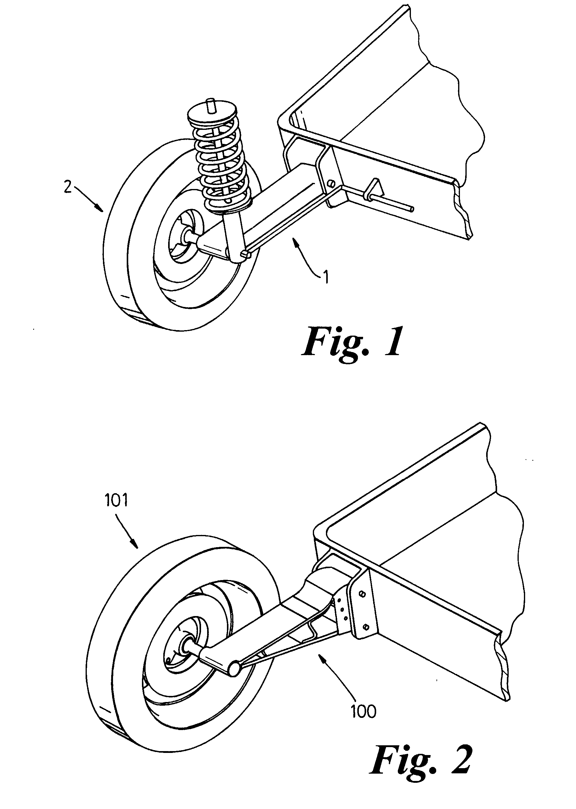
[0089] FIGS. 2 to 7 of the accompanying drawings illustrate a first embodiment of a passive suspension assembly 100 for a wheel 101 of a vehicle in accordance with one aspect of the present invention.

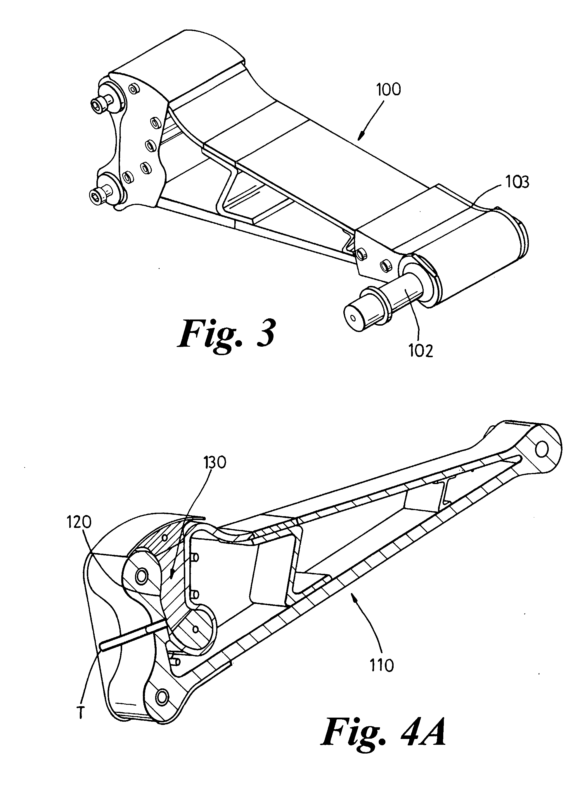
[0090] The complete assembly 100 is shown prior to fitting to a vehicle in FIG. 3 including stub axle assembly 102 and brake mounting assembly 103, with the floating shoe arrangement, in isometric view. The complete and partial section views in FIG. 4. A & B show the internals of the assembly. Finally, FIGS. 5 and 6 of the accompanying drawings are cross sectional schematic views.

[0091] Referring primarily to those figures, the assembly 100 comprises a suspension arm 110 of unitary construction which at least partially defines a control space 120 whose volume changes as the arm deflects, and a restoring means 130 which is enclosed within the control space 120 defined by the arm 110. The restoring means 120 in this example is a pressurised gas contained within a bladder held within a s...


PUM

PropertyMeasurementUnit
Fractionaaaaaaaaaa
Pressureaaaaaaaaaa
Volumeaaaaaaaaaa

Abstract

An apparatus for connecting a load to a support comprises a flexible suspension arm of unitary construction and restoring means, the suspension arm being so constructed and arranged to define at least two spaced apart members whose relative location determines the volume of a space which contains the restoring means, deflection of the flexible suspension arm in use causing the arm to deform to alter the relative position of the two spaced apart members, thereby altering the volume of the space and so compressing the restoring means. The apparatus is especially suited to suspension assemblies for vehicles.

Description


Claims


Application Information

Patent Timeline
Owner TRW LIMITED
Why Eureka
Try Eureka