Connection arrangement for superconductor cable shields

a superconductor cable and connection arrangement technology, applied in the direction of electrically conductive connections, superconducting magnets/coils, magnetic materials, etc., can solve the problems of not being able to envisage connecting the shield directly to the earth, increasing the quantity of cryogenic fluid consumed for cooling the superconductor, and affecting the overall electrical efficiency of the installation

Inactive Publication Date: 2008-01-10
NEXANS
View PDF3 Cites 11 Cited by
  • Summary
  • Abstract
  • Description
  • Claims
  • Application Information

AI Technical Summary

Benefits of technology

[0009] Advantageously, said cryogenic sheath may be connected to the cryostat by means of a “Johnston” type coupli...

Problems solved by technology

For high-voltage cables, the magnitude of this current can be high (e.g. 2400 amps (A)) and it is therefore not possible to envisage connecting the shield directly to the earth.
Nevertheless, interconnecting the shields by a resistive cable leads to thermal and electrical loses by the Joule effect, and thus to an increase in the quantity of cryogenic fluid consumed for cooling the superconductor, and leads to a drop in the e...

Method used


Image

  • Connection arrangement for superconductor cable shields
  • Connection arrangement for superconductor cable shields
  • Connection arrangement for superconductor cable shields

Examples


first embodiment

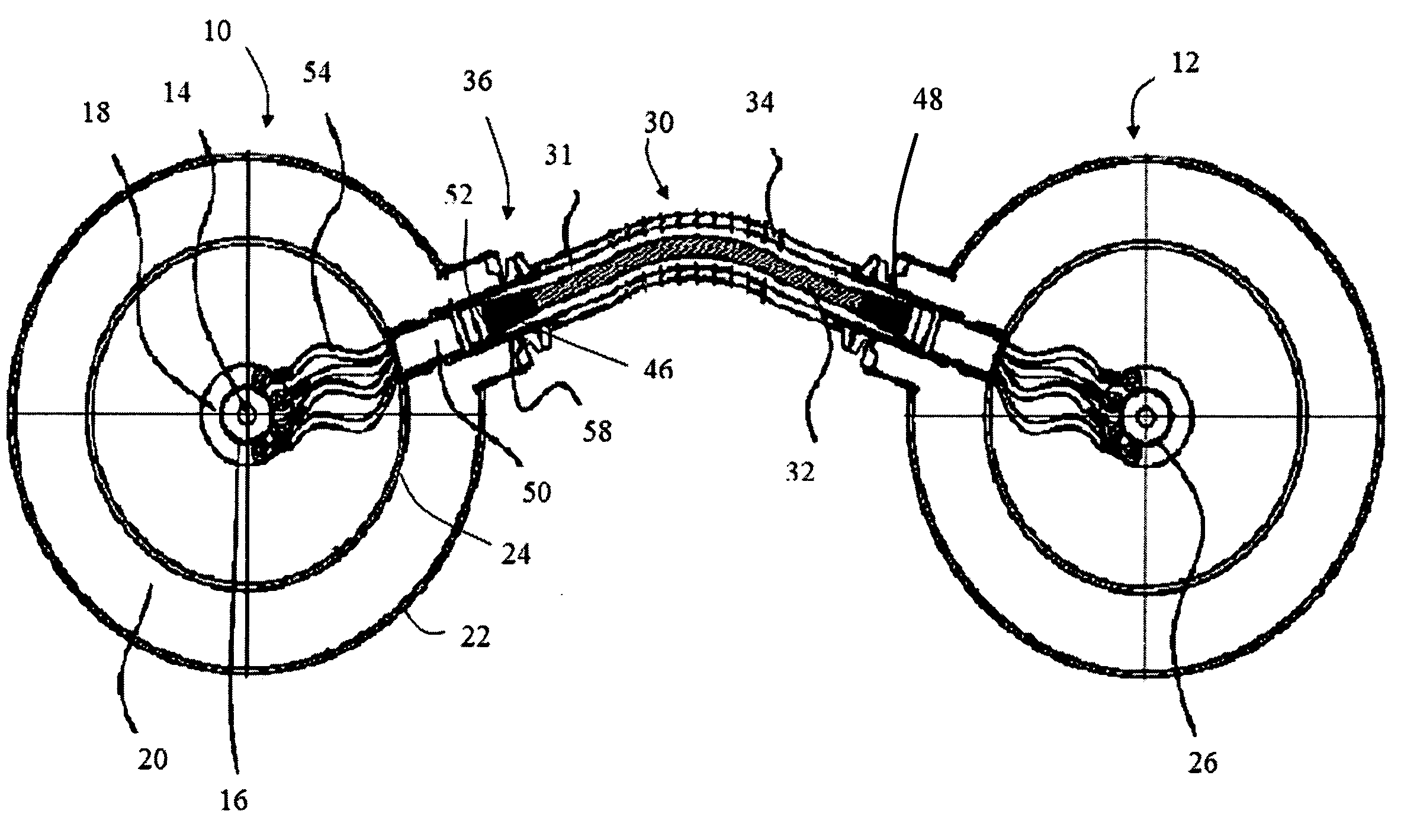
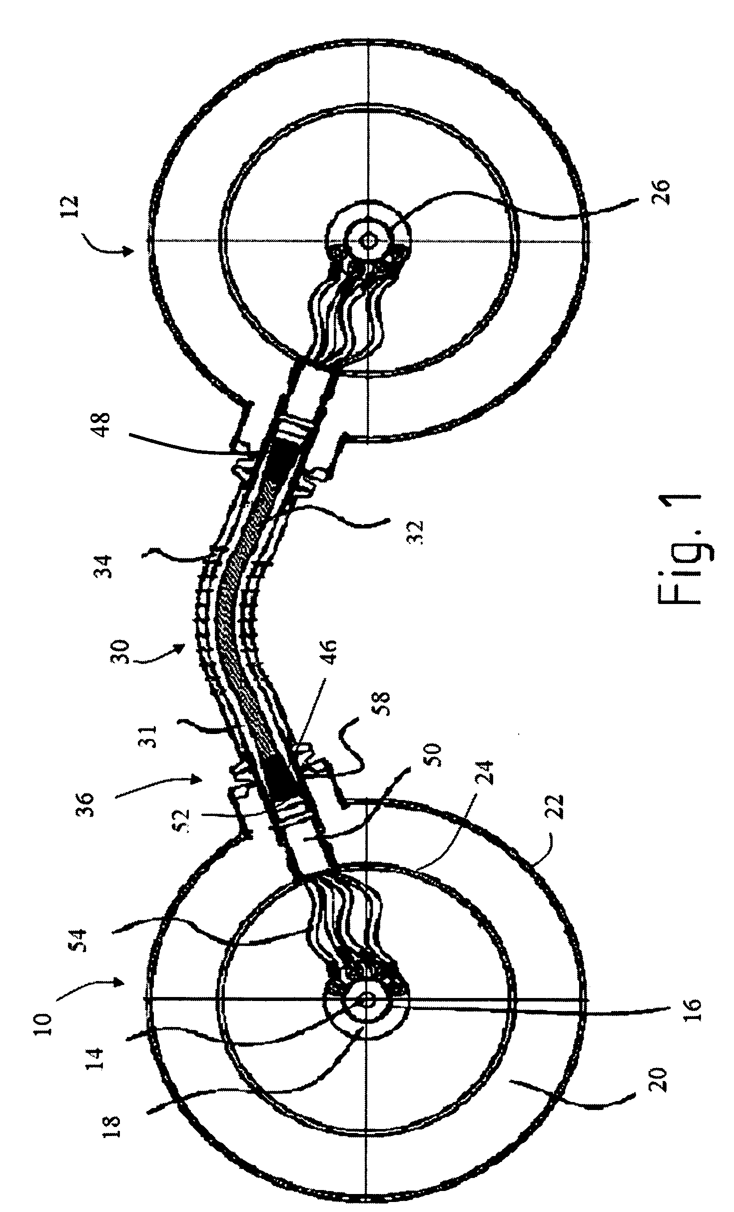
[0028] In a first embodiment, cooling is provided by thermal conduction along the connection piece 50 and the support 40 of the link superconductor 32. The cryogenic fluid contained in the cryostat 20 does not pass into the cryogenic sheath 34. It is then necessary to provide sealing between the cryostat 20 and the sheath 34. This sealing may be made by clamping the connection piece 50 against the inside wall 24 of the cryostat 20, or by clamping between the male and female portions of the coupling 58.

second embodiment

[0029] In a second embodiment, the link superconductor 32 is cooled by direct contact with the cryogenic fluid of the cryostat 20. Under such circumstances, the connection part 50 does not need to be fastened in leaktight manner and passages may be provided through said connection piece so as to allow the cryogenic fluid of the cryostat 20 to pass into the space 31 between the cryogenic sheath 34 and the link superconductor 32.

[0030] In this second embodiment, it may be observed that the link superconductor 32 is also cooled in part by thermal conduction. This makes it possible, particularly if the flow rate of cryogenic fluid through the connection piece 50 is limited, to supplement the direct cooling by convection of the cryogenic fluid against the link superconductor with the thermal conduction along the support 40 and the connection means 36.

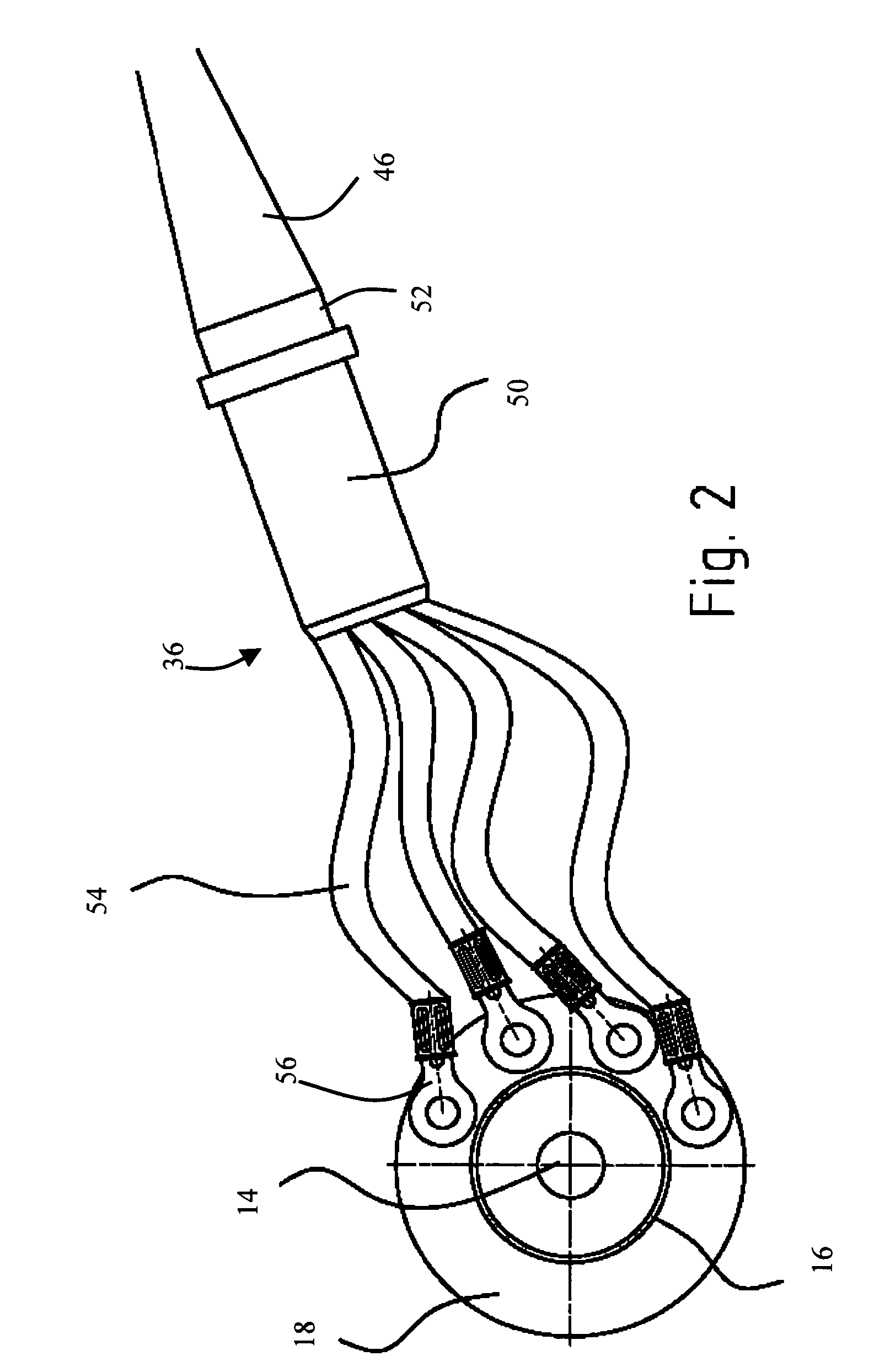
[0031] The various ways in which the connection piece 50 is connected to the junction element 18, as described with reference to FIGS. 1, ...


PUM


Abstract

A connection arrangement for electrically interconnecting the shields of so-called “cold-dielectric” superconductor cables in the context of a muiltiphase superconductive electrical link, each superconductor cable comprising a central superconductor presenting superconductivity at cryogenic temperature, electrical insulation surrounding the central conductor, a shield surrounding the electrical insulation, and a cryostat surrounding said shield. According to the invention, the arrangement comprises a superconductive link between said shields, said superconductive link comprising a link superconductor and a cryogenic sheath surrounding said link superconductor, each of the two ends of said link superconductor being connected to a respective one of said shields by connection means that are both electrically and thermally conductive. The invention is particularly applicable to high voltage electricity.

Description

RELATED APPLICATION [0001] This application is related to and claims the benefit of priority from French Patent Application No. 04 52827, filed on Dec. 1, 2004, the entirety of which is incorporated herein by reference. FIELD OF THE INVENTION [0002] The present invention relates to a connection arrangement for cold-dielectric superconductor cable shields, in particular the shields of superconductor cables for different phases. BACKGROUND OF THE INVENTION [0003] Transporting electricity by means of high voltage superconductor cables enables high currents to be transported while using cable sections that are much smaller than is possible with conventional cables made of resistive electrical conductors, while simultaneously limiting electrical losses along the cable, in particular losses due to the Joule effect, since that phenomenon is extremely weak with superconductivity. In order to reduce losses, electricity is transported in multiphase alternating current (AC) form, generally thr...

Claims


Application Information

Patent Timeline
IPC IPC(8): H01F6/00
CPCH01R4/68H01B12/02H01B12/14H01B12/16H02G15/34
Inventor MIREBEAU, PIERRESCHIPPL, KLAUSSCHMIDT, FRANKLALLOUET, NICOLAS
Owner NEXANS
Why Eureka
Try Eureka