Supercharge Your Innovation With Domain-Expert AI Agents!

Image projection system

a projection system and projection laser technology, applied in the field of projection lasers, can solve problems such as loss of revenue, and achieve the effect of ensuring the visibility of cautionary and directional lines and attracting more attention to signag

Inactive Publication Date: 2008-01-10
MURPHY TERRY
View PDF16 Cites 28 Cited by
  • Summary
  • Abstract
  • Description
  • Claims
  • Application Information

AI Technical Summary

Benefits of technology

"The invention aims to make safety and directional lines on factory and warehouse floors more visible and easily removable. It uses animation graphics to make these lines more noticeable to people. The goal is to attract more attention to the signs on the floor."

Problems solved by technology

Often equipment must be shut down and processes halted to refresh the safety lines, resulting in lost revenue.

Method used


Image

  • Image projection system
  • Image projection system
  • Image projection system

Examples


Embodiment Construction

[0010]Before explaining the disclosed embodiment of the present invention in detail it is to be understood that the invention is not limited in its application to the details of the particular arrangement shown, since the invention is capable of other embodiments. Also, the terminology used herein is for the purpose of description and not of limitation.

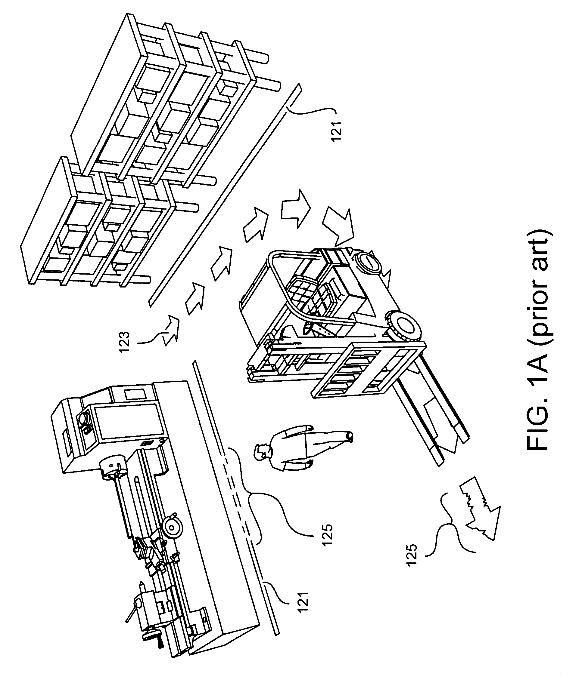
[0011]In today's factory and warehouse environments, floor safety and organization are regulated more tightly than ever. Plant management recognizes that the greater organized a plant is, the more efficient it will operate, and the safer it will be for its operators and guests.

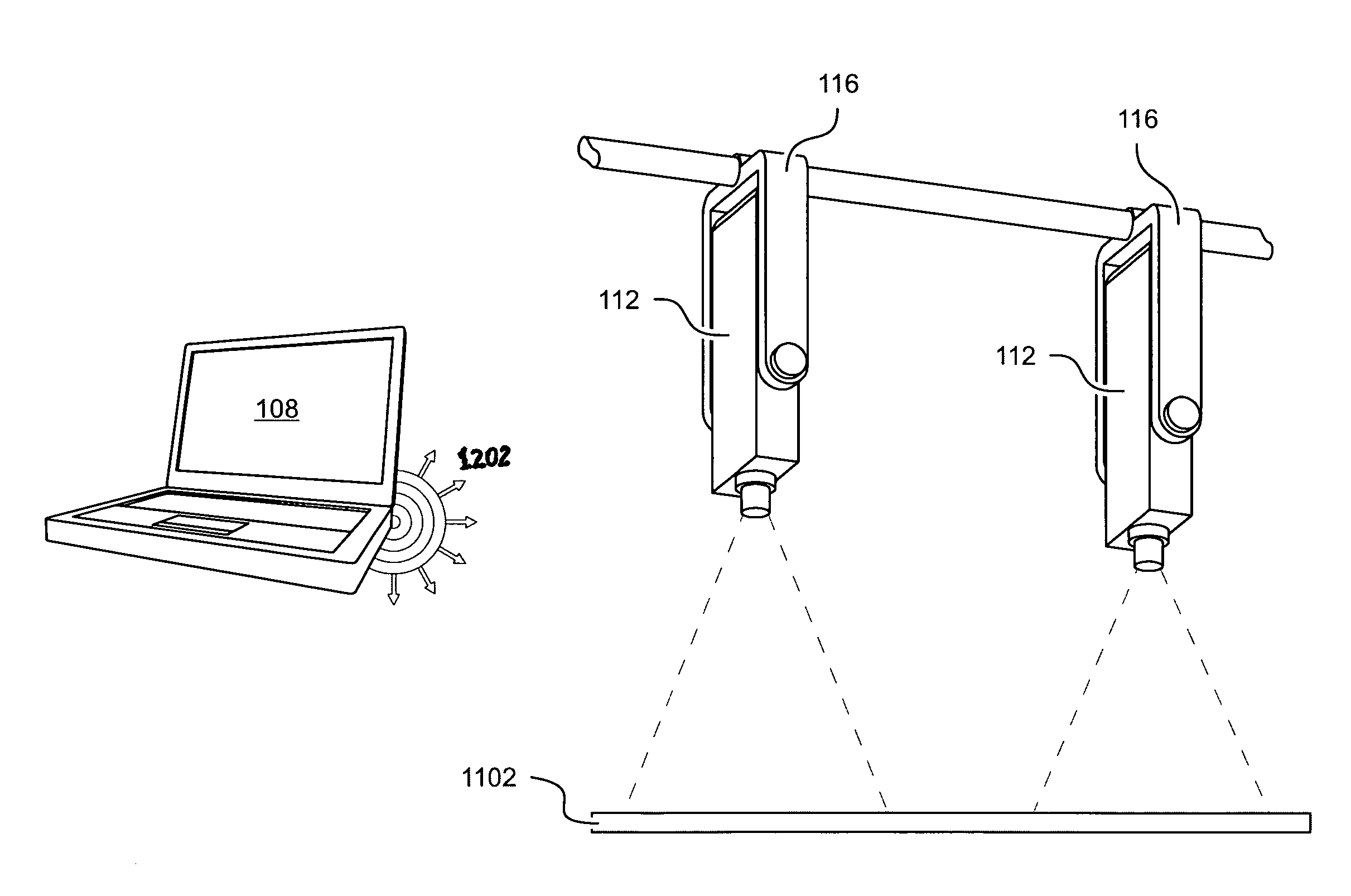
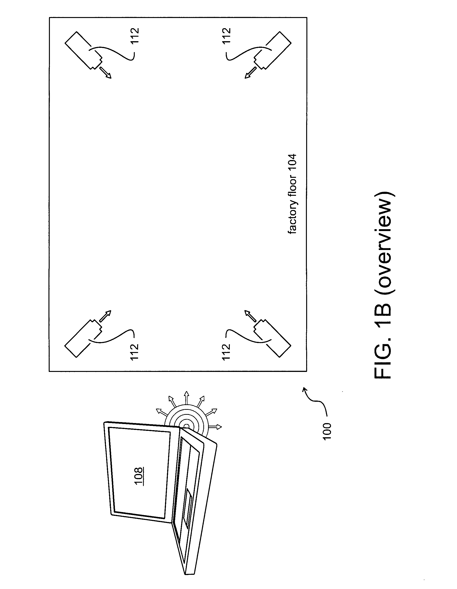
[0012]Accordingly, one function of the present invention is to provide an improved type of factory or warehouse floor labeling. The present invention replaces paint, tape, and other floor-labeling media with projected laser light. Doing so eliminates the negative impact of direct, wear-and-tear, dirt, and tire marks that require periodic maintenance on the paint...


PUM


Abstract

A laser projector and software are disclosed. The software controls the laser projector for factory and warehouse floor-room marking and signage.

Description

CROSS-REFERENCE TO RELATED APPLICATIONS[0001]This application claims priority to U.S. Provisional Application No. 60 / 819,327, which was filed on Jul. 7, 2006.FIELD OF THE INVENTION[0002]This invention relates generally to projection lasers.BACKGROUND OF THE INVENTION[0003]This invention was conceived to eliminate the need to continually paint lines on the floor in factory or warehouse environments. Often equipment must be shut down and processes halted to refresh the safety lines, resulting in lost revenue. Consequently, a means of maintaining the visibility of safety lines without having to shut down factory equipment or warehouse processes is desired. As shown in FIG. 1A, the prior art floor system includes painted lines 121 and arrows 123 having worn areas 125. Consequently, a means of using an image projection system to manage a factory or warehouse floor is desired.SUMMARY OF THE INVENTION[0004]It is the object of this invention to maintain the visibility of cautionary and dire...

Claims


Application Information

Patent Timeline
Patent Type & Authority Applications(United States)
IPC IPC(8): G08B5/00F21S8/00G08B21/00
CPCG03B21/00G09F19/18H04N9/3191H04N9/3129H04N5/74
Inventor MURPHY, TERRY
Owner MURPHY TERRY
Features
  • R&D
  • Intellectual Property
  • Life Sciences
  • Materials
  • Tech Scout
  • Unparalleled Data Quality
  • Higher Quality Content
  • 60% Fewer Hallucinations
Learn More