
Trapping method for digital color printing

Inactive Publication Date: 2008-01-10
KYOCERA DOCUMENT SOLUTIONS INC
View PDF14 Cites 39 Cited by
  • Summary
  • Abstract
  • Description
  • Claims
  • Application Information

AI Technical Summary

Benefits of technology

[0006] The invention describes a system for trapping in electrophotographic color printing and related technologies for printing or display in which the final image is an overlay of multiple components subject to alignment errors. Trapping is a technique, well-known in principle, for reducing the visibility of alignment errors, also known as registration errors, by selectively adjusting the boundaries of image objects to overlap slightly and thereby conceal the errors. In the present invention the new methods apply to digital systems, especially to electrophotographic color printers in desktop publishing systems. The new methods offer improvements in simplicity of implementation, performance, cost, customization, compatibility with color printer controllers, automatic operation and visually acceptable results.
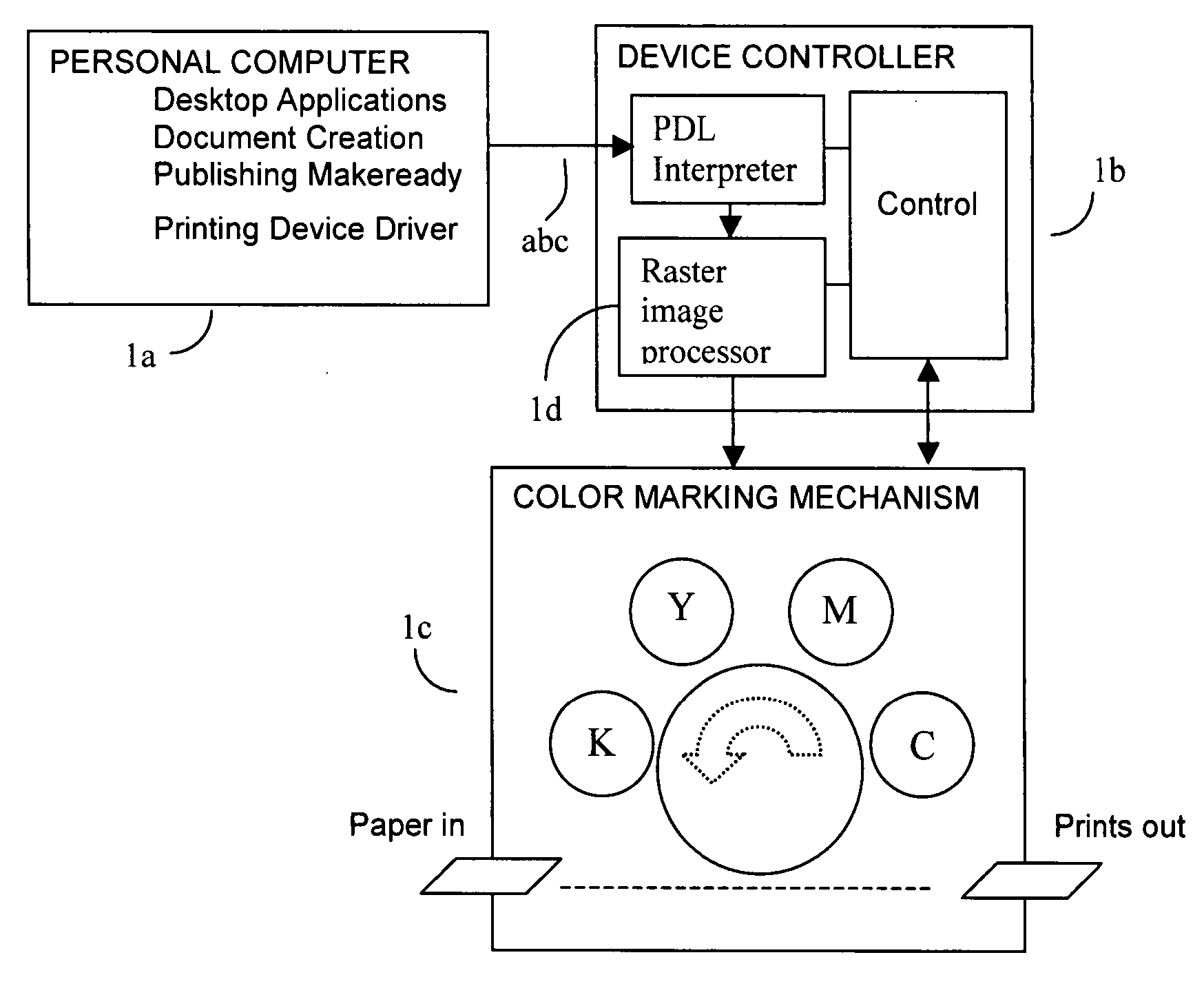
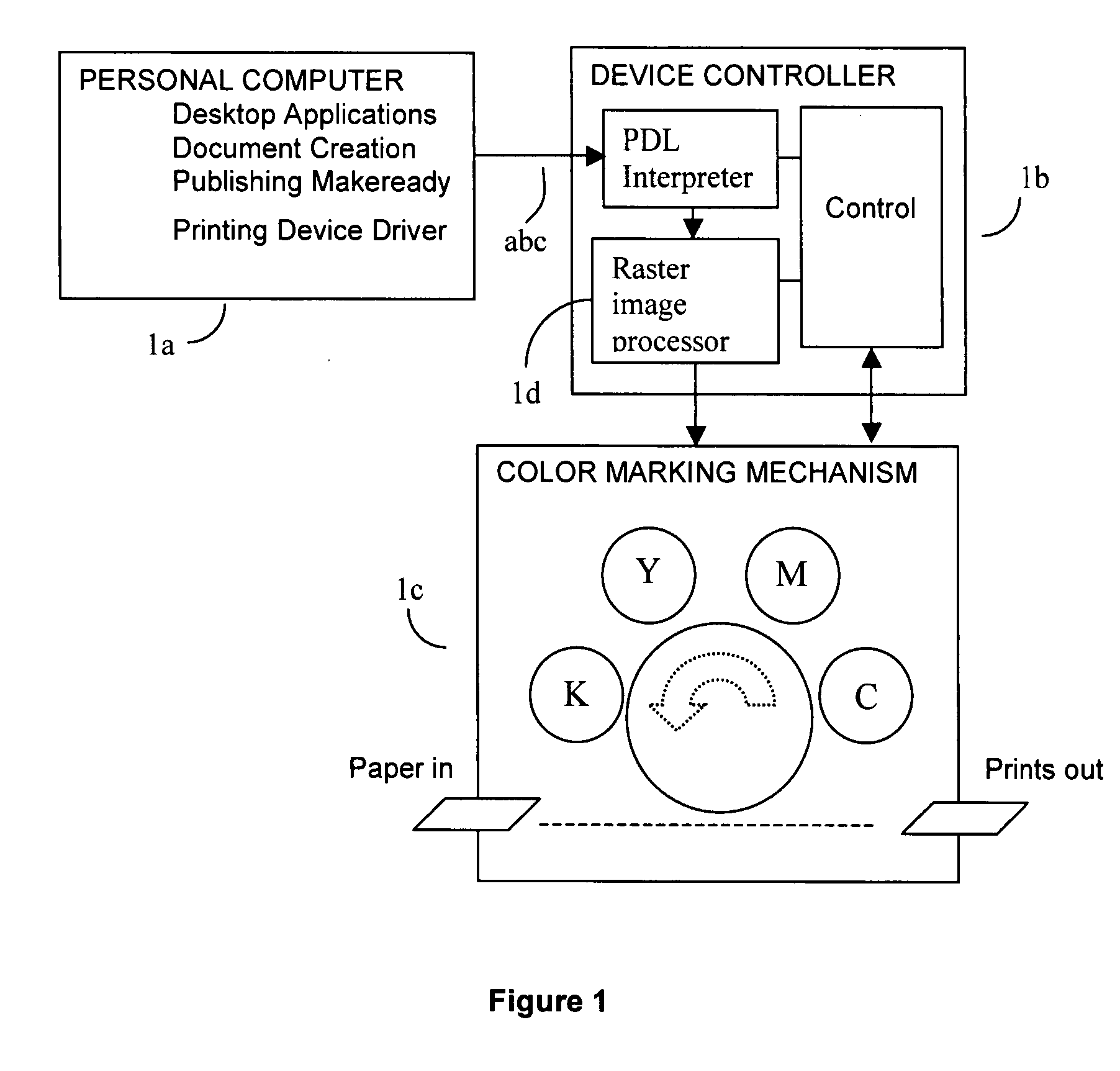
[0024] As is well known, in the PDL datastream supplied to the RIP the digital image format is a vector or object representation; in the output to the device it is a raster format. In-RIP trapping, in turn, can be accomplished at either of these levels or in a hybrid combination. The traps can be calculated as the page description lays down each object on the raster or alternatively the entire page can be rasterized before any trapping is performed. The former case, known as object-based trapping, has the advantages that object type can be taken into account to handle complex trapping rules and performance is favored because object information such as the path and color of the entire outline are available and do not have to be calculated. Object-based trapping has the disadvantages that it is complicated in cases where several objects are overlaid on top of each other and transparent objects need to be ‘flattened’ (a process in which the final color of transparent objects is determined by applying the transparency value to the color of the transparent object and to the color of the background) before any trapping can be performed on them. Also, it can conveniently be implemented only in software, unfavorably impacting RIP performance.
[0033] In its application to printing with color electrographic printers, the invention requires as input raster data for the color planes either for each plane separately or in packed form with data for all colors for each pixel. Thus, for example in the case of four colors CMYK, in planar form the data would be organized into four arrays of pixels and in packed form it would be as a single array with each element representing all four color values for one pixel. In one possible realization the invention is implemented in ISO C++. It is a layered architecture that allows pluggable and interchangeable components in the form of templatized classes that can be combined by means of the C++ template mechanism to generate the code for a complete trapper. Trapping is a computationally intensive process, and since the characteristics of electrographic printers vary greatly, it must be able to handle a wide variety of real world situations. This goal conflicts directly with those of trapping in real time with high performance and low cost. Therefore a hybrid approach has been utilized that capitalizes on the expressivity of C++ templates and operator overloading as well as the terse and fast assembly code generated by C code, resulting in a flexible architecture that does not compromise on speed and cost.

Problems solved by technology

However, because this mode takes effect at low color density levels, it rarely provides perceptible quality improvement and it may be omitted where performance and cost take priority.

Method used


Image

  • Trapping method for digital color printing
  • Trapping method for digital color printing
  • Trapping method for digital color printing

Examples


Embodiment Construction

Object Edge Detection

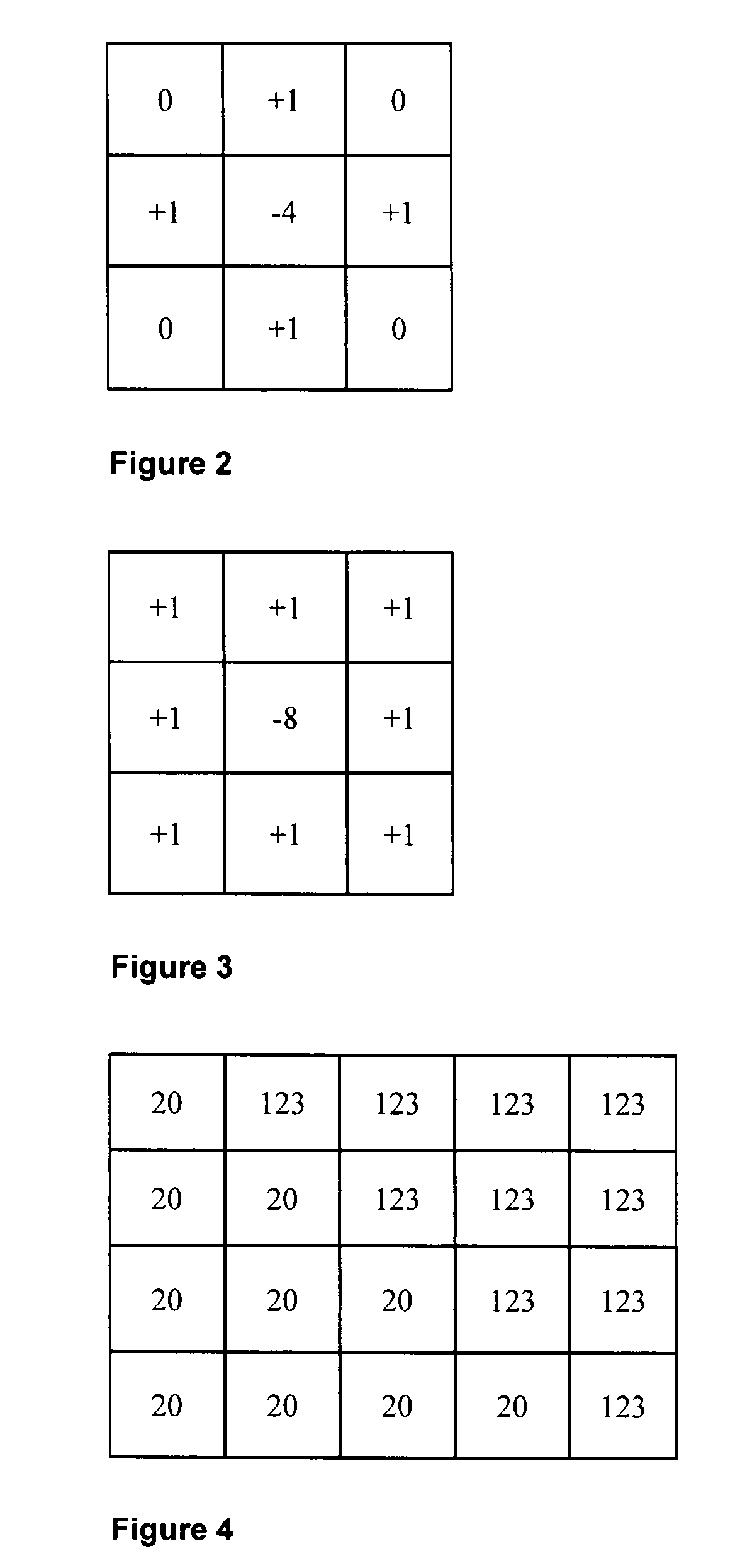
[0063] Object edge detection is performed on each color plane independent of other color planes. The well-known method of convolution with a so-called Laplacian kernel is used for each pixel in the color plane. The result can be thought of as, in effect, a new plane of convolved values whose dimensions correspond pixel-for-pixel with the original plane. For efficiency and resource reasons in a practical software implementation for trap widths up to one pixel only three scanlines are convolved at a time. This three scanline window starts at the top of the page raster image and moves downwards to the bottom of the page one scanline at a time as each scanline is trapped. For trap widths up to two pixels, five scanlines are used in the same way. In practical hardware, convolutions are calculated, but they are not saved to a “new plane.” Thus a vertical “swath” of five convolution values (for 1.5 and 2.0-pixel traps) is generated in a hardware pipeline.

[0064] The ...


PUM


Abstract

A system and method for trapping in electrophotographic color printing and related technologies for printing or display in which the final image is an overlay of multiple components subject to alignment errors. Trapping is based on the cyan (C), magenta (M), and black (K) planes. There are four steps as follows: detect object edges on each of the four color planes; detect coincident and opposing edge transitions on each pair of planes (CM, CK, and KM); determine which plane to trap, i.e., to extend object across edge; and generate trap on that plane using a simple trap generation rule and a single trap generation rule.

Description

CROSS REFERENCE TO RELATED APPLICATIONS [0001] This application claims priority from U.S. Provisional Application Ser. No. 60 / 795,901, filed on Apr. 28, 2006, which is incorporated herein by reference in its entirety.FIELD [0002] The present invention applies to color printing by electrophotographic technology in which the final print consists of an overlay of multiple impressions. For example, using impressions in the colors cyan, magenta, yellow and black respectively, a visual equivalent of a full color view can be printed. In principle, it also applies to any electronic digital method for printing or display in which the final print or image consists of more than one print plane component or image plane component where the components overlaid are not perfectly in register and the visibility of the errors can be reduced by a technique known as trapping. BACKGROUND [0003] In the terminology of traditional printing the term trapping (more particularly wet trapping and dry trapping)...

Claims


Application Information

Patent Timeline
IPC IPC(8): G06F15/00
CPCH04N1/58
Inventor GANDHI, LAKHBIRWESTERVELT, ROBERTSCHMIDT, KENNETH A.SU, DONGPEIABKARIAN, ALFREDRALEY, MARK
Owner KYOCERA DOCUMENT SOLUTIONS INC
Learn More