Apparatus at a flat card for cotton, synthetic fibers or the like, having a carding element

a technology applied in the field of artificial fibers and flat cards, can solve the problems of increasing the temperature level of the cylinder and adjacent components, undesirably large deformations, and deformation of the fixed carding element, and achieve the effect of reducing the temperature gradient and the deformation produced thereby, and better removal of hea

Inactive Publication Date: 2008-01-17
TRUETZSCHLER GMBH & CO KG
View PDF8 Cites 0 Cited by
  • Summary
  • Abstract
  • Description
  • Claims
  • Application Information

AI Technical Summary

Benefits of technology

[0006] As a result of the measures in accordance with the invention, a considerable proportion of the heat is removed to the outside so that the carrier element remains dimensionally stable in operation even when exposed to heat. It is advantageous that the profiled member cross-section is open to the outside. As a result, the temperature gradient and the deformation produced thereby are drastically reduced. In addition, the profiled member according to the invention, having open cross-sections and an optimised mass distribution, brings about better removal of heat (cooling rib effect) and so reduces the temperature level of the cylinder and of adjacent components. The thermal expansion of the components of the flat card is reduced.

Problems solved by technology

The heat produced during the carding process is to a large extent removed by way of the fixed carding elements to the outside, the temperature gradient required for the purpose within the cross-section of the profiled member resulting in deformation of the fixed carding element.
In the case of profiled member cross-sections which are enclosed on all sides, relatively large temperature gradients occur, giving rise to undesirably large deformations.
In addition, the enclosed pockets of air have a disadvantageous effect in the case of those profiled members, causing the profiled members to act like thermal insulation and to raise the temperature level of the cylinder and of adjacent components.

Method used


Image

  • Apparatus at a flat card for cotton, synthetic fibers or the like, having a carding element
  • Apparatus at a flat card for cotton, synthetic fibers or the like, having a carding element
  • Apparatus at a flat card for cotton, synthetic fibers or the like, having a carding element

Examples


Embodiment Construction

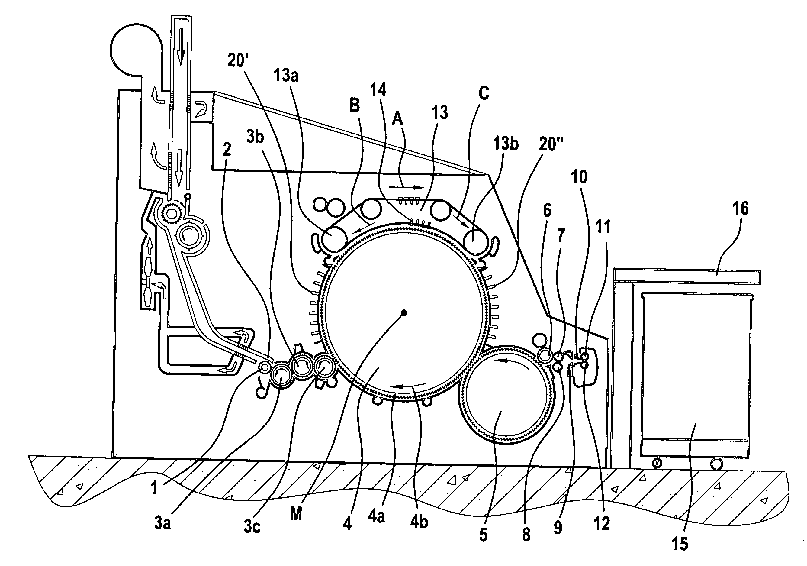
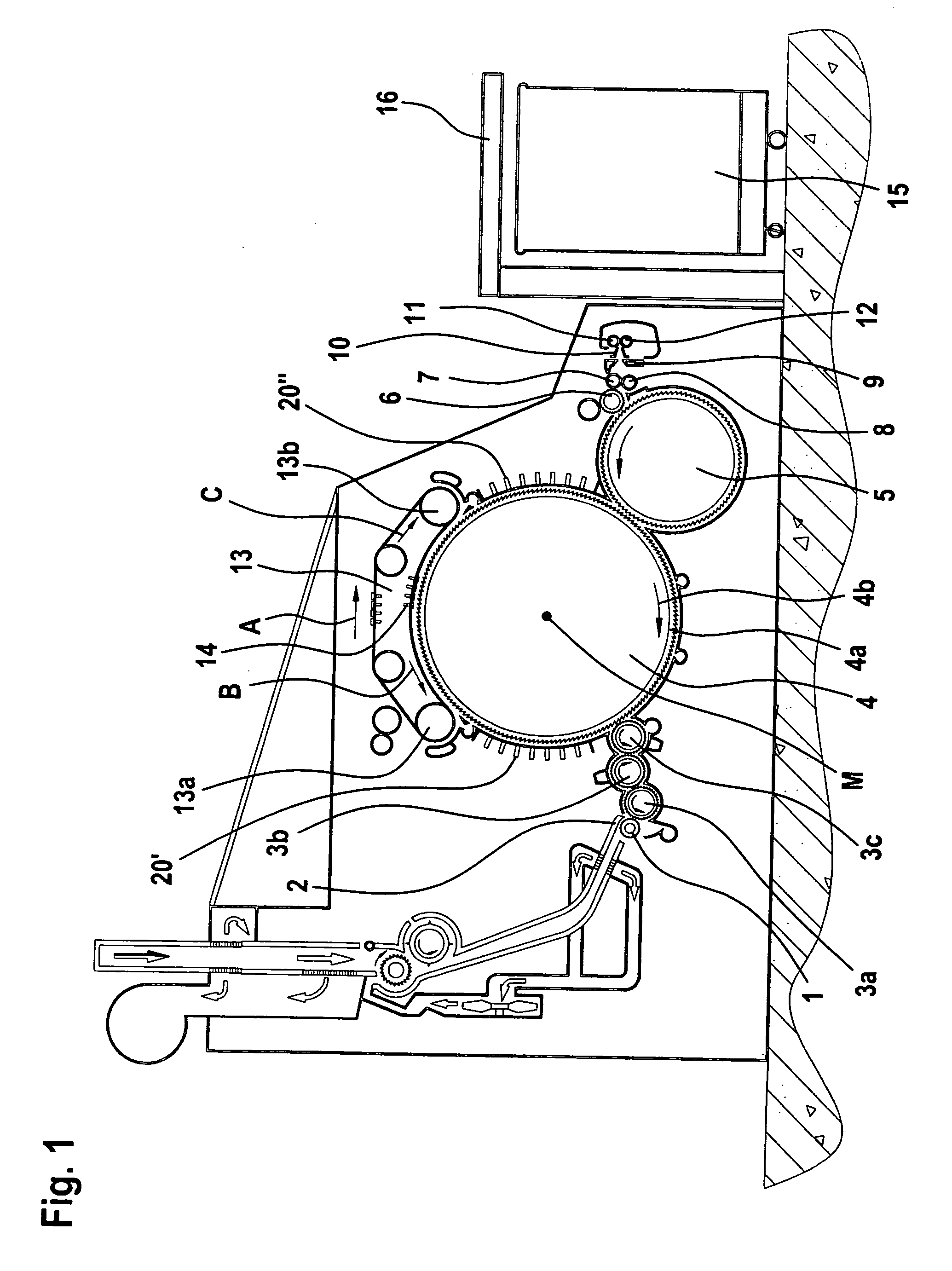
[0020]FIG. 1 shows a flat card, for example a Trützschler TC 03 ™ flat card, having a feed roller 1, feed table 2, lickers-in 3a, 3b, 3c, cylinder 4, doffer 5, stripper roller 6, nip rollers 7, 8, web-guiding element 9, web funnel 10, delivery rollers 11, 12, revolving card top 13 having card top guide rollers 13a, 13b and flats 14, can 15 and can coiler 16. The directions of rotation of the rollers are indicated by curved arrows. Reference letter M denotes the centre (axis) of the cylinder 4. Reference numeral 4a denotes the clothing and reference numeral 4b denotes the direction of rotation of the cylinder 4. The arrow A indicates the working direction. The curved arrows drawn inside the rollers denote the directions of rotation of the rollers. The flat card according to FIG. 1 is provided with has a number of fixed carding elements 20′, 20″, which may be of one or more of the kinds shown in FIG. 2, FIG. 3 or FIG. 4 or may be of any other construction according to the invention.

[...


PUM

PropertyMeasurementUnit
widthaaaaaaaaaa
widthaaaaaaaaaa
temperature distributionaaaaaaaaaa

Abstract

In an apparatus at a flat card for cotton, synthetic fibres and the like, wherein at least one stationary carding element comprising a carrying element with at least one clothing element is associated with a clothed roller, for example a cylinder, the tips of the clothing elements and the tips of the clothing of the roller lie opposite one another with a spacing and the carrying element has a hollow space. In order for the carrying element to be dimensionally stable in operation even when exposed to heat, the cross-sectional shape of the carrying element does not include an enclosed hollow space, and the opening is arranged in a region remote from the tips of the clothing element.

Description

CROSS REFERENCE TO RELATED APPLICATION [0001] This application claims priority from German Patent Application No. 10 2006 003 958.0 dated Jan. 26, 2006, the entire contents of which are incorporated herein by reference. BACKGROUND OF THE INVENTION [0002] The invention relates to an apparatus at a flat card for cotton, synthetic fibres and the like, wherein at least one stationary carding element comprising a carrying element with at least one clothing element is associated with a clothed roller, for example a cylinder. [0003] Fixed carding elements are increasingly being used in textile machines, especially in roller cards and flat cards. These fixed carding elements consist of a profiled carrier member and clothing strips attached thereto (1 to 3 strips per profiled carrier member). The profiled carrier members for fixed carding elements are currently made in the form of profiled members of extruded aluminum which are enclosed on all sides. In the case of a known apparatus (GB 1 54...

Claims


Application Information

Patent Timeline
Patent Type & Authority Applications(United States)
IPC IPC(8): D01G15/08
CPCD01G15/24
Inventor SCHMITZ, THOMAS
Owner TRUETZSCHLER GMBH & CO KG
Why Eureka
Try Eureka