Turbine engine combustion chamber with tangential slots

a turbine engine and combustion chamber technology, applied in the direction of machines/engines, mechanical equipment, lighting and heating apparatus, etc., can solve the problems of loss of clamping transiting between the flanges, cracks in the region of the bolt connection on the cowling and/or the chamber bottom, etc., to achieve convenient assembly and sufficient flexibility

Active Publication Date: 2008-01-17
SN DETUDE & DE CONSTR DE MOTEURS DAVIATION S N E C M A
View PDF21 Cites 19 Cited by
  • Summary
  • Abstract
  • Description
  • Claims
  • Application Information

AI Technical Summary

Benefits of technology

[0006] The principal object of the present invention is therefore to overcome such drawbacks by proposing an annular combustion chamber archit...

Problems solved by technology

In practice, this type of combustion chamber architecture poses many problems.
In particular, the different elements of the combustion chamber have large manufacturing tolerances, which leads to stacking up of the tolerances resulting in poor closing up between these elements when the combustion chamber is being assembled, which creates a loss as rega...

Method used


Image

  • Turbine engine combustion chamber with tangential slots
  • Turbine engine combustion chamber with tangential slots
  • Turbine engine combustion chamber with tangential slots

Examples


Embodiment Construction

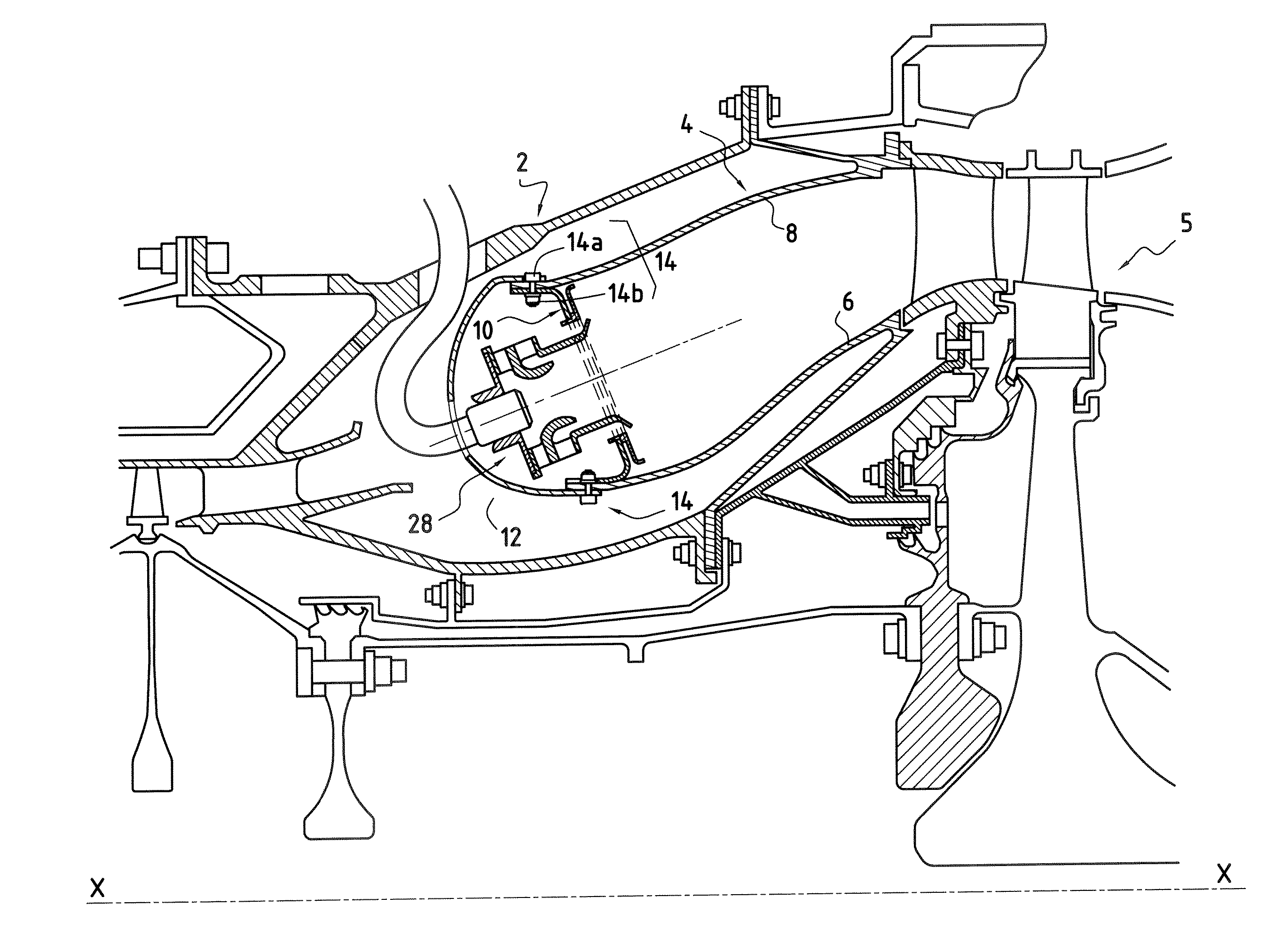
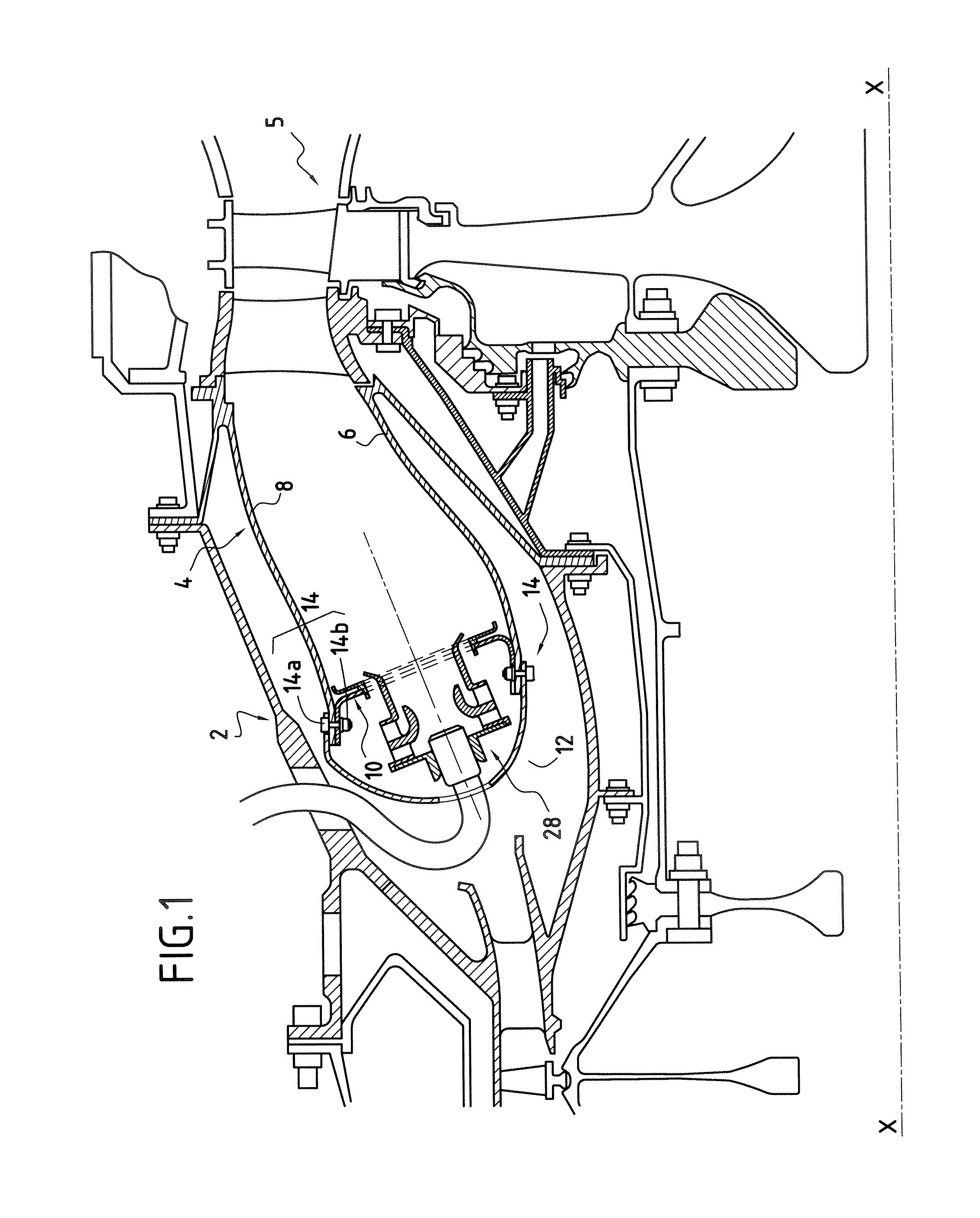
[0014] FIGS. 1 to 3 illustrate a combustion chamber for a turbine engine according to the invention.

[0015] A turbine engine of this kind, for example an aeronautical one, comprises in particular a compression section (not shown) wherein air is compressed before being injected into a chamber housing 2, and then into a combustion chamber 4 mounted inside the latter.

[0016] The compressed air is introduced into the combustion chamber and mixed with fuel before being burned therein. The gases resulting from this combustion are then directed to a high-pressure turbine 5 arranged at the output of the combustion chamber.

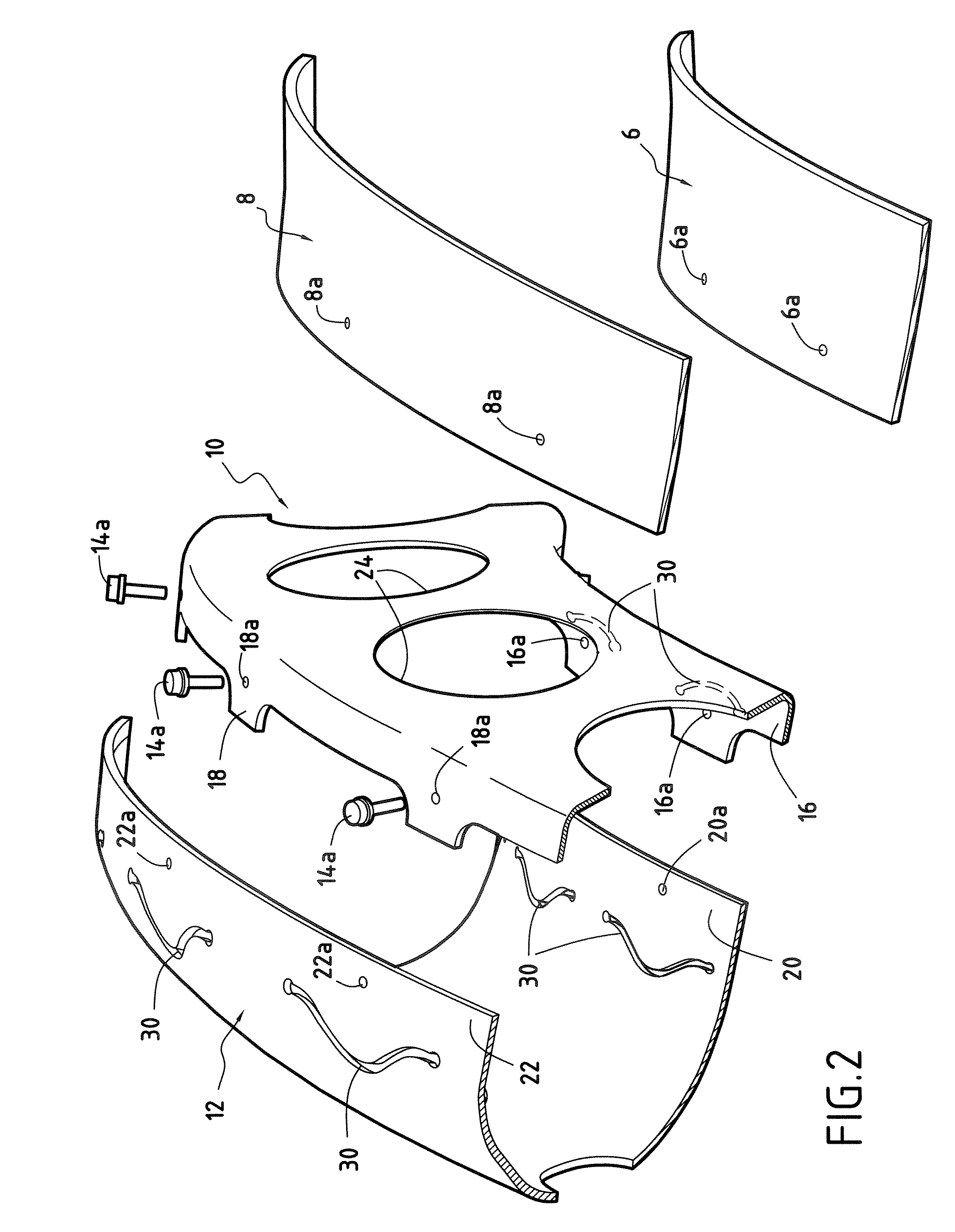
[0017] The combustion chamber 4 is of annular type. It is made up of an inner annular wall 6 and an outer annular wall 8 which extend in a substantially longitudinal direction with respect to the longitudinal axis X-X of the turbine engine.

[0018] These longitudinal walls 6, 8 are joined upstream (with respect to the direction of flow of the combustion gases in the combus...


PUM


Abstract

The invention concerns a turbine engine annular combustion chamber, comprising longitudinal walls (6, 8) connected by a transverse chamber bottom (10) and a single-piece cowling (12), the chamber bottom (10) and the cowling (12) each comprising an inner flange (16, 20) and an outer flange (18, 22) each with a plurality of holes made in it for the passage of fixing systems (14a, 14b) for fixing the cowling on the chamber bottom. Each fixing system has associated with it at least one tangential slot (30) formed on the corresponding flange (16, 18) of the chamber bottom (10) and/or on the corresponding flange (20, 22) of the cowling (12), each slot (30) being formed in the immediate vicinity of the corresponding fixing system (14a, 14b).

Description

BACKGROUND OF THE INVENTION [0001] The present invention relates to the general field of annular combustion chambers for turbine engines equipped with a single-piece protective cowling for the fuel injection systems [0002] A turbine engine annular combustion chamber is generally made up of two longitudinal walls generated by revolution (an outer wall and an inner wall) which are connected upstream by a transverse wall forming the chamber bottom. [0003] The present invention relates more particularly to combustion chambers that also comprise a single-piece cowling mounted upstream of the chamber bottom. The cowling is used in particular to protect the fuel injection systems which are mounted on the chamber bottom. [0004] Assembling these different elements of the combustion chamber is carried out by means of bolt connections mounted at the inner and outer walls. More precisely, the chamber bottom and the cowling each comprise an inner flange and an outer flange on which respectively ...

Claims


Application Information

Patent Timeline
Owner SN DETUDE & DE CONSTR DE MOTEURS DAVIATION S N E C M A
Why Eureka
Try Eureka