
Method, device and system for determining direction of arrival of signal

a signal direction and signal technology, applied in the direction of direction finders, instruments, measurement devices, etc., can solve the problems of affecting the direct signal, multipath signals resulting from mirror reflection of the response pulse off the reflector are typically of significant amplitude, etc., and achieve accurate estimation of the doa , the effect of reducing the number of errors caused by the presence of multipath signals

Inactive Publication Date: 2008-01-17
SONY CORP
View PDF5 Cites 29 Cited by
  • Summary
  • Abstract
  • Description
  • Claims
  • Application Information

AI Technical Summary

Benefits of technology

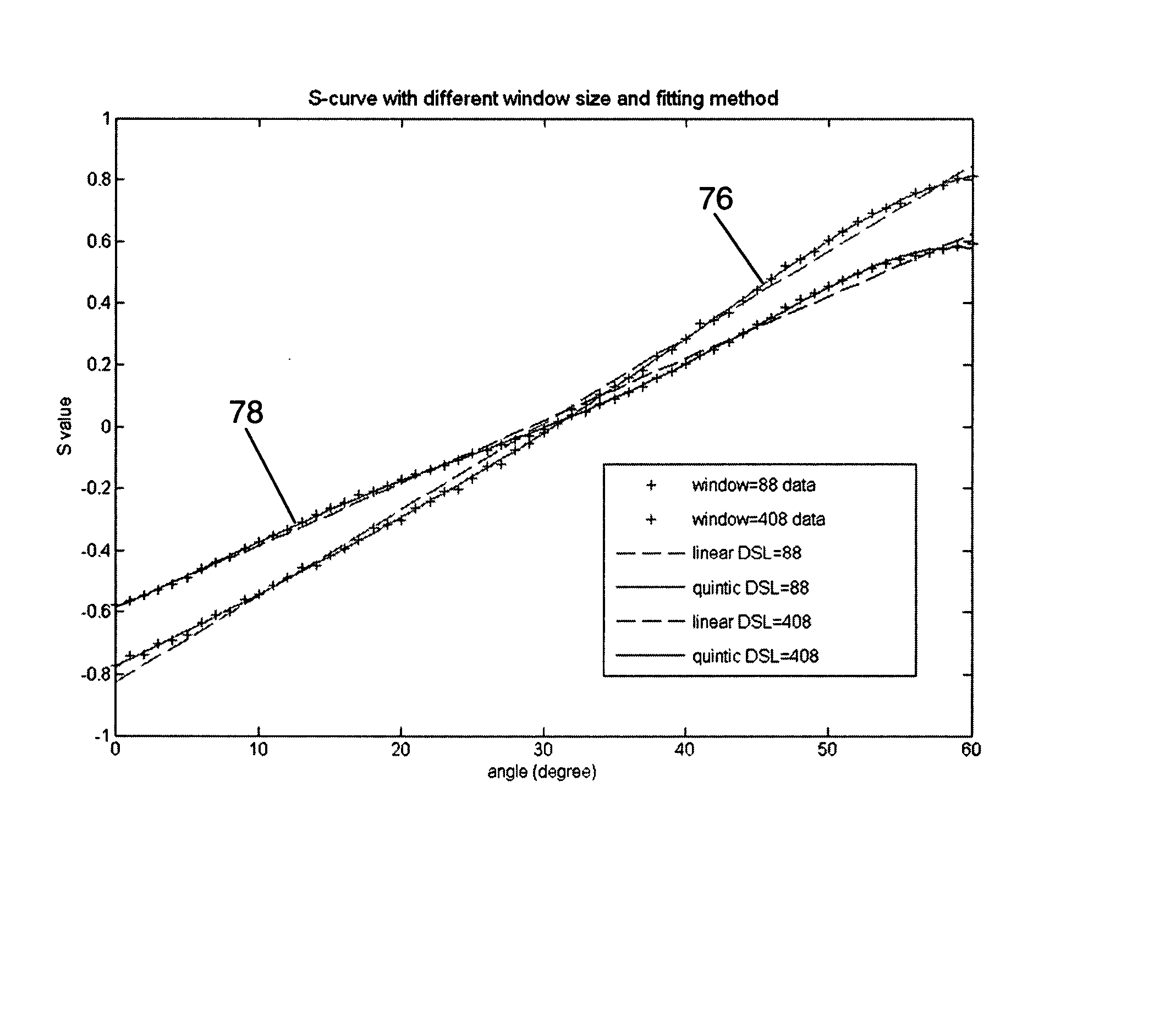
[0009] In order to meet the above, embodiments of the present invention provide a method, device and system for which may determine a DOA of a signal that give a substantially accurate estimate of the DOA even in applications with severe multipath effects. By utilising a leading portion of the signal in the determination of the DOA, errors introduced due to the presence of multipath signals may be substantially reduced.
[0012] Preferably, the calibration data obtained from a calibration process may be established from a leading portion of a calibration signal. This accounts for differences in the effective UWB spectrum of the calibration signals when different segments of the calibration signals are used, thereby providing a more accurate estimate of the DOA. The calibration data obtained from the calibration process may be stored in a lookup table or as a function derived from plotting the calibration data as a calibration curve. The calibration process preferably is performed in a free space environment.

Problems solved by technology

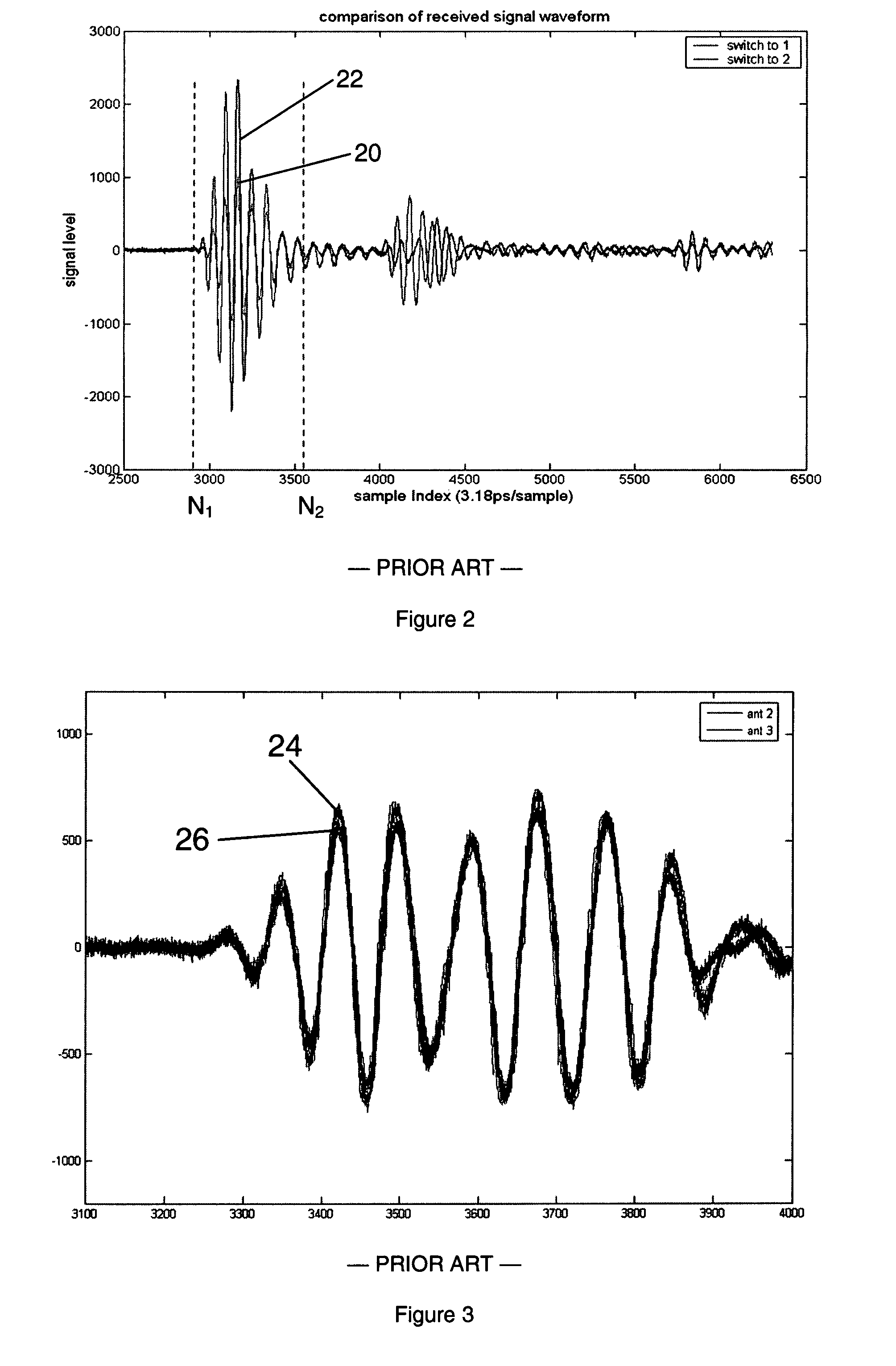
However, in applications where the prior art UWB positioning system operates in proximity, for example, less than 1 metre (m), to a sizable reflector such as a wall, multipath signals resulting from mirror reflection of the response pulse off the reflector are typically of significant amplitudes and tend to interfere with the direct signal.

Method used


Image

  • Method, device and system for determining direction of arrival of signal
  • Method, device and system for determining direction of arrival of signal
  • Method, device and system for determining direction of arrival of signal

Examples


Embodiment Construction

[0029] The detailed description set forth below in connection with the appended drawings is intended as a description of embodiments of the invention, and is not intended to represent the only form in which the present invention may be practiced. It is to be understood that the same or equivalent functions may be accomplished by different embodiments that are intended to be encompassed within the spirit and scope of the invention. In the drawings, like numerals are used to indicate like elements throughout.

[0030] Referring now to FIG. 4, a system 50 for determining a DOA of a signal is shown. The system 50 comprises a transceiver 52 and a transponder 54. The transceiver 52 includes multiple directional antennas 56, a processor 58 and a memory 60 for storing calibration data. The transponder 54 includes an omni-directional antenna 62. The signal whose DOA is to be determined is generated by the transponder 54 in response to receipt of a UWB pulse. Adjacent pairs of the directional a...


PUM


Abstract

A method, device and system for determining a DOA of a signal are described. Determination of the DOA of the signal may include receiving first and second UWB waveforms of the signal at one or more antennas of a UWB transceiver. A window may be defined in the first and second UWB waveforms such that the window is defined in a leading portion of the signal. First and second amplitude values of the respective first and second UWB waveforms in the window may be calculated. An amplitude ratio may be calculated with the first and second amplitude values and compared with calibration data to determine the DOA of the signal.

Description

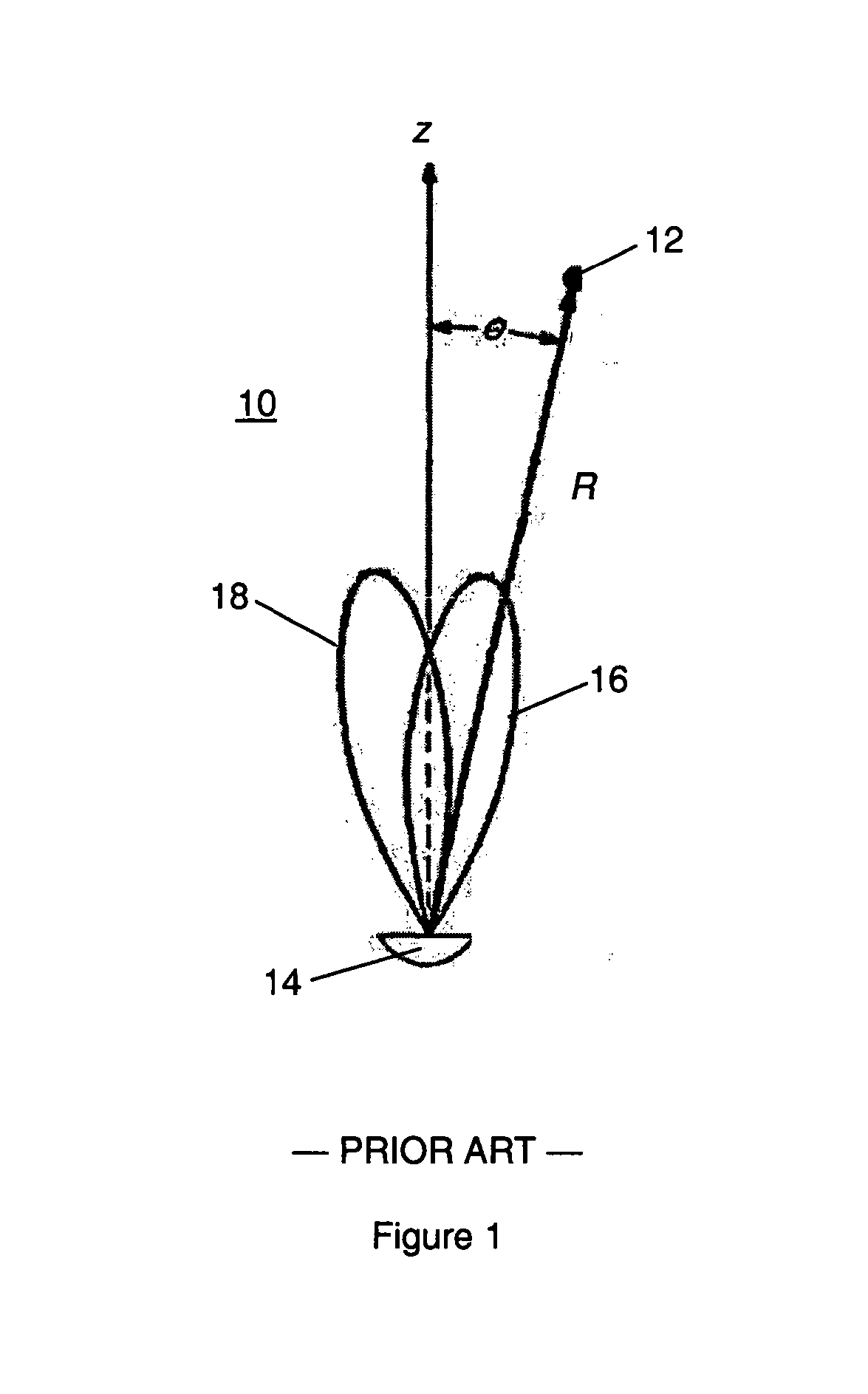
CROSS-REFERENCE TO RELATED APPLICATIONS [0001] This application claims priority from Singapore Patent Application No. SG 200604421-8 filed in the Singapore Patent Office on Jun. 27, 2006, the entire content of which is incorporated herein by reference. FIELD OF THE INVENTION [0002] The present invention relates to wireless positioning systems and more particularly to a method, device and system for determining a DOA of a signal. BACKGROUND OF INVENTION [0003] Monopulse, also known as simultaneous lobe comparison, is a technique for determining the direction of arrival (DOA) of radiation. The radiation may emanate from an active source, for example, a transceiver, a transponder or a beacon, or a passive source, that is, a target or scatterer that reradiates some of the power incident on it. The working principle of the monopulse technique for DOA determination is described below with reference to FIG. 1. [0004] Referring now to FIG. 1, a schematic top plan view of a conventional mono...

Claims


Application Information

Patent Timeline
Patent Type & Authority Applications(United States)
IPC IPC(8): G01S5/04G01S3/28
CPCG01S13/4418
Inventor XU, JINMA, YUGANGSUN, XIAOBINGOKADA, KANZO
Owner SONY CORP
Learn More