Magnetic head for perpendicular magnetic recording and method of manufacturing same

a technology of magnetic recording and perpendicular head, which is applied in the direction of magnetic recording head, data recording, instruments, etc., can solve the problem of difficulty in defining the throat height with accuracy

Active Publication Date: 2008-01-17
HEADWAY TECH INC +1
View PDF13 Cites 37 Cited by
  • Summary
  • Abstract
  • Description
  • Claims
  • Application Information

AI Technical Summary

Benefits of technology

[0018]It is an object of the invention to provide a magnetic head for perpendicular magnetic recording having a structure in which a pole layer faces toward a shield layer with a gap layer disposed in between, the head being capable of ...

Problems solved by technology

In a magnetic disk drive of the perpendicular magnetic recording system that exhibits a better capability of writing on a recording medium than the longitudinal magnetic recording system, in particular, if the above-mentioned skew is created, problems arise, such as a phenomenon in which data ...

Method used


Image

  • Magnetic head for perpendicular magnetic recording and method of manufacturing same
  • Magnetic head for perpendicular magnetic recording and method of manufacturing same
  • Magnetic head for perpendicular magnetic recording and method of manufacturing same

Examples


first embodiment

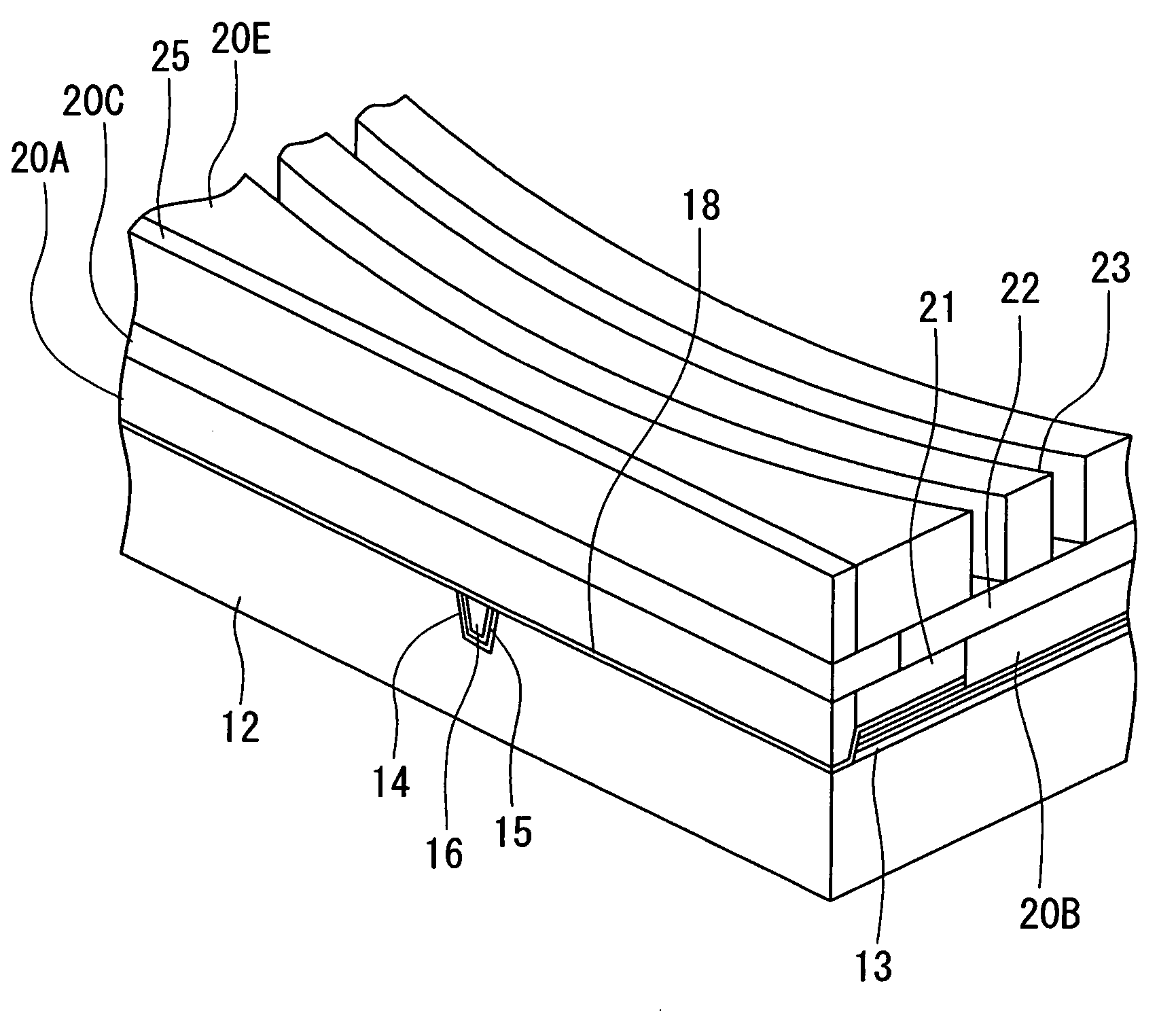
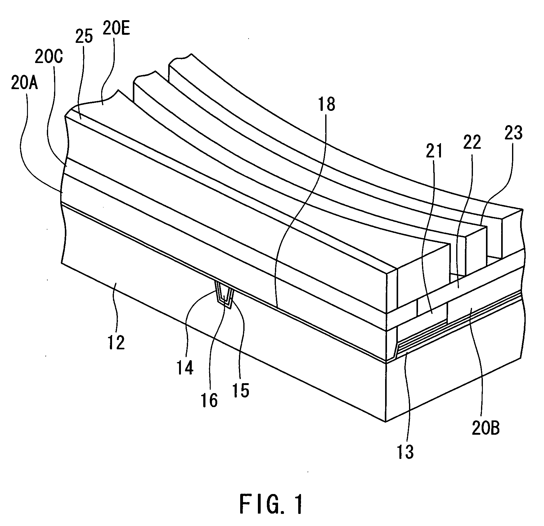
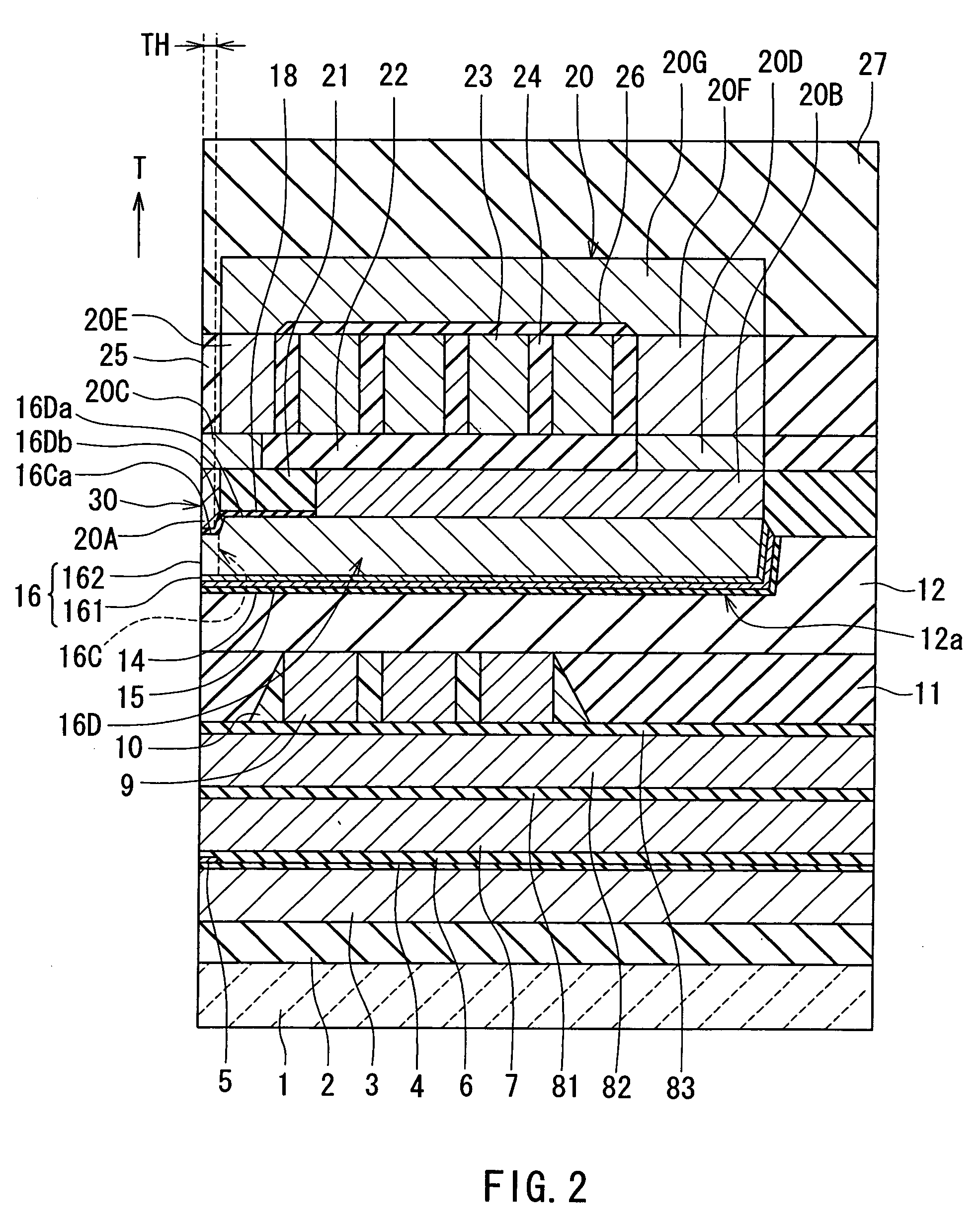
[0050]Preferred embodiments of the invention will now be described in detail with reference to the accompanying drawings. Reference is now made to FIG. 1 to FIG. 4 to describe the configuration of a magnetic head for perpendicular magnetic recording of a first embodiment of the invention. FIG. 1 is a perspective view illustrating a portion of the magnetic head of the first embodiment in a neighborhood of the medium facing surface. FIG. 2 is a cross-sectional view for illustrating the configuration of the magnetic head of the embodiment. FIG. 2 illustrates a cross section orthogonal to the medium facing surface and a surface of a substrate. The arrow indicated with T in FIG. 2 shows the direction of travel of a recording medium. FIG. 3 is a front view of the medium facing surface of the magnetic head of the embodiment. FIG. 4 is a top view of the pole layer and the shield layer of the magnetic head of the embodiment.

[0051]As shown in FIG. 2 and FIG. 3, the magnetic head for perpendic...

second embodiment

[0121]Reference is now made to FIG. 14 and FIG. 15 to describe a magnetic head and a method of manufacturing the same of a second embodiment of the invention. FIG. 14 is a cross-sectional view for illustrating the configuration of the magnetic head of the second embodiment. FIG. 14 illustrates a cross section orthogonal to the medium facing surface and the surface of the substrate. The arrow indicated with T in FIG. 14 shows the direction of travel of a recording medium. FIG. 15 is a front view of the medium facing surface of the magnetic head of the embodiment.

[0122]The magnetic head of the second embodiment comprises an insulating layer 28 that covers at least part of the coil 23 in place of the insulating layer 24 of FIG. 2. The insulating layer 28 is made of photoresist, for example. The shield layer 20 of the second embodiment comprises a third layer 20H in place of the third layer 20E, the coupling layer 20F and the fourth layer 20G of the FIG. 2. One of end faces of the third...

third embodiment

[0126]Reference is now made to FIG. 16 to describe a magnetic head and a method of manufacturing the same of a third embodiment of the invention. FIG. 16 is a top view illustrating a pole layer and a shield layer of the magnetic head of the third embodiment.

[0127]The first layer 20A of the shield 20 of the third embodiment incorporates: a middle portion 20A1 including a portion opposed to the pole layer 16 with the gap layer 18 disposed in between; and two side portions 20A2 and 20A3 located at positions outside the middle portion 20A1 along the direction of track width. A length H11 of the middle portion 20A1 taken in the direction orthogonal to the medium facing surface 30 is uniform, regardless of the position along the direction of track width. The length H11 of the middle portion 20A1 taken in the direction orthogonal to the medium facing surface 30 falls within a range of 0.1 to 0.3 μm inclusive, for example. A width W11 of the middle portion 20A1 is equal to or greater than t...


PUM


Abstract

A magnetic head comprises a pole layer, a shield layer, a gap layer disposed between the pole layer and the shield layer, and a coil. The shield layer incorporates a first layer, a second layer, a third layer and a fourth layer that are disposed on the gap layer one by one. The first layer has an end face located in a medium facing surface. The second layer has: a first surface located in the medium facing surface; a second surface touching the first layer; and a third surface opposite to the second surface. The third layer touches the third surface of the second layer. An end face of each of the third and fourth layers closer to the medium facing surface is located at a distance from the medium facing surface.

Description

BACKGROUND OF THE INVENTION[0001]1. Field of the Invention[0002]The present invention relates to a magnetic head for perpendicular magnetic recording that is used for writing data on a recording medium by means of a perpendicular magnetic recording system and to a method of manufacturing such a magnetic head.[0003]2. Description of the Related Art[0004]The recording systems of magnetic read / write devices include a longitudinal magnetic recording system wherein signals are magnetized in the direction along the surface of the recording medium (the longitudinal direction) and a perpendicular magnetic recording system wherein signals are magnetized in the direction orthogonal to the surface of the recording medium. It is known that the perpendicular magnetic recording system is harder to be affected by thermal fluctuation of the recording medium and capable of implementing higher linear recording density, compared with the longitudinal magnetic recording system.[0005]Like magnetic heads...

Claims


Application Information

Patent Timeline
IPC IPC(8): G11B5/127
CPCG11B5/1278
Inventor SASAKI, YOSHITAKAITOH, HIROYUKITANEMURA, SHIGEKIARAKI, HIRONORILI, DONG-HONGSHIMIZU, TATSUSHISHIMIZU, TATSUYA
Owner HEADWAY TECH INC
Why Eureka
Try Eureka