
Method for processing a digital gray value image

a gray value and image technology, applied in image enhancement, image analysis, instruments, etc., can solve the problems of deterioration of image resolution and reduced noise, and achieve the effect of reducing image noise and higher image sharpness

Active Publication Date: 2008-01-17
CARL ZEISS SMT GMBH
View PDF6 Cites 11 Cited by
  • Summary
  • Abstract
  • Description
  • Claims
  • Application Information

AI Technical Summary

Benefits of technology

[0004] It is an object of the invention to provide a method with which a digital gray value image can be so processed that a reduced image noise and simultaneously a higher image sharpness is achieved.
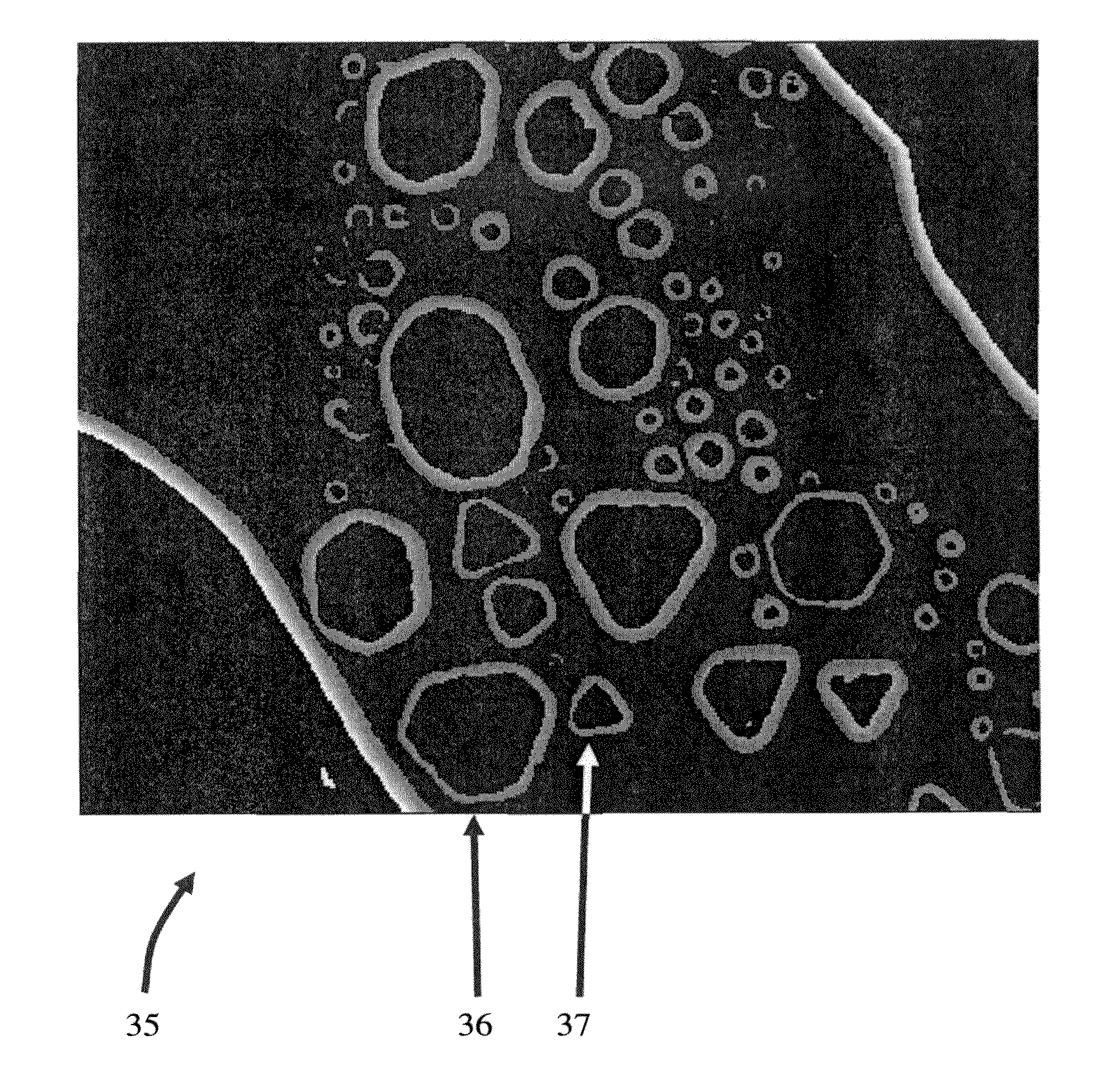
[0013] According to an embodiment of the invention, the binary edge image is created via a gradient image generated on the basis of the gray value image. For generating the gradient image, preferably a difference operator is utilized which is selected from the group comprising: a Sabel operator, a Prewitt operator, a Laplace operator, a Kirsch operator and a Roberts operator. Other difference operators can be utilized if a gradient image can be generated therewith. Preferably, the gray value image is subjected to a smoothing process in advance of the generation of the gradient image. This can, for example, take place with the use of a median filter. A smoothing process of this kind functions to reduce the noise intensity in the originally recorded gray value image.
[0015] If closed paths are not sought so that, for example, also half circles can be determined, a first threshold value can be assigned to the gradient image. Gradient image points with a brightness magnitude above the first threshold value are set to logic 1 and gradient image points having a brightness magnitude below the first threshold value are set to logic 0 so that a binary edge image is generated wherein the gradient image points, which are set to logic 1, form line areas around edges and the gradient image points, which are set to logic 0, form a background. In this way, a binary edge image with line areas around edges is created on a black background. The first threshold value amounts to preferably a fourth of the maximum gradient in the gradient image. Such a relatively low threshold value is advantageous because, in this way, only a relatively small amount of image data is masked out from the gradient image present as a gray value image.

Problems solved by technology

The principal problem when utilizing a noise suppression filter for the entire image is that the noise is reduced but the resolution of the image is deteriorated.

Method used


Image

  • Method for processing a digital gray value image
  • Method for processing a digital gray value image
  • Method for processing a digital gray value image

Examples


Embodiment Construction

[0036] A raster electron microscope 100 having a monitor 110 is shown in FIG. 15. The monitor can display a gray value image. The raster electron microscope 100 includes an electron source 101 which can emit an electron beam 102 which is focused by electromagnetic lenses 103 and 104. After passing an aperture diaphragm 105, the electron beam is deflected by deflecting coils 106 onto a specimen 107, which is to be investigated, and is passed linearly in a raster manner over the surface of the specimen. When the electron beam impinges upon the specimen, secondary electrons are, inter alia, liberated and these secondary electrons are detected by a detector 108. The signals of the detector are conducted to a downstream amplifier 109 to which the monitor 110 is coupled and with which a gray value image can be displayed.

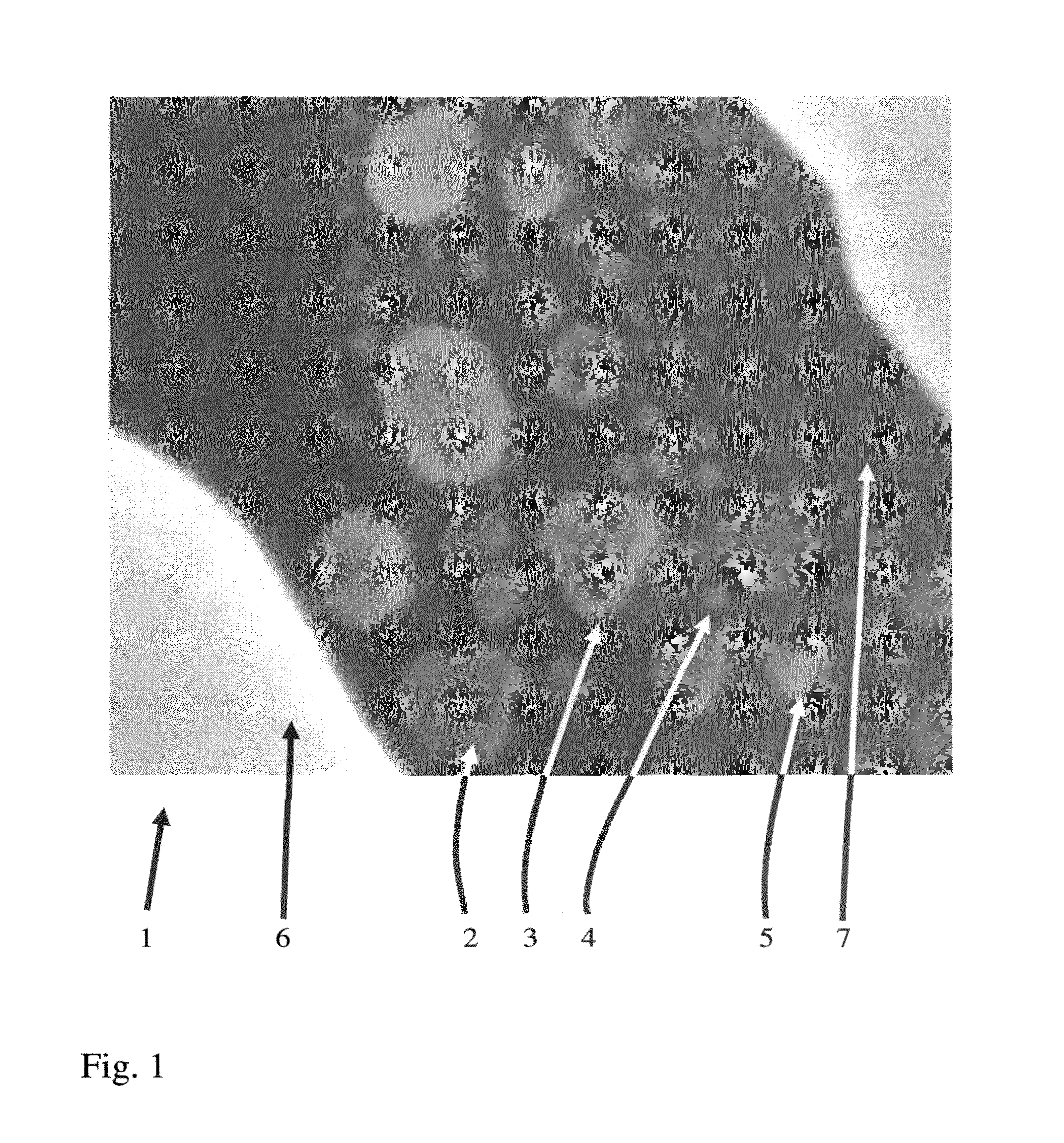
[0037] In FIG. 1, a digital gray value image 1 is shown which is recorded with a raster electron microscope (see step S1 in the flow diagram of FIG. 13A). The digital gra...


PUM


Abstract

A method for processing a digital gray value image includes the steps of: generating a binary edge image from the gray value image so that edges present in the gray value image are determined as line areas around the edges; applying a sharpness algorithm in the gray value image within regions which correspond to the line areas; and, carrying out a smoothing process in the gray value image within regions which lie outside of the line areas so that an additional smoothed, sharpened gray value image is generated.

Description

CROSS REFERENCE TO RELATED APPLICATION [0001] This application claims priority of German patent application no. 10 2006 026 843.1, filed Jun. 9, 2006, the entire content of which is incorporated herein by reference. FIELD OF THE INVENTION [0002] The invention relates to a method for processing a digital gray value image. The invention further relates to a computer system and a computer program for carrying out such a method as well as an image recording arrangement operating with a computer program of this kind. BACKGROUND OF THE INVENTION [0003] A digitally recorded gray value image contains image data which are shown in different gray values. If such images are formed, for example, by means of an electron microscope, an electron beam scans line by line over the specimen area to be investigated. If this is done at high speed, then noise or a granulation arise which clearly and disturbingly are superposed on the actual image data. An image recorded in such a manner can only be detec...

Claims


Application Information

Patent Timeline
IPC IPC(8): G06K9/40
CPCG06T5/20G06T2207/20012G06T5/003G06T5/002G06T2207/20032G06T5/73G06T5/70
Inventor ALBIEZ, MICHAELHAYN, ARMINEVANS, OWAIN
Owner CARL ZEISS SMT GMBH
Learn More