
Imaging apparatus

Inactive Publication Date: 2008-01-17
ELMO CO LTD
View PDF6 Cites 31 Cited by
  • Summary
  • Abstract
  • Description
  • Claims
  • Application Information

AI Technical Summary

Benefits of technology

[0010]The present invention is directed to an imaging apparatus equipped with a camera in a pivotally rotatable manner both in a vertical direction and in a horizontal direction. The imaging apparatus includes: abase that has a built-in vertical rotation driving source to generate a driving force for pivotal rotation of the camera in the vertical direction and a built-in horizontal rotation driving source to generate a driving force for pivotal rotation of the camera in the horizontal direction; and a camera unit including the camera. The camera unit is pivotally supported on the base by a camera unit pivotal support structure to allow pivotal rotation of the camera in the vertical direction. A vertical rotation transmission mechanism transmits the driving force of the vertical rotation driving source, as power of the pivotal rotation of the camera in the vertical direction, to the camera unit, so as to rotate the camera unit including the camera in the vertical direction. The transmission of the driving force generated by the vertical rotation driving source enables the camera unit with the camera mounted on the base to be rotated in the vertical direction.
[0022]In another aspect of the imaging apparatus of the preferable embodiment, the camera unit pivotal support structure for pivotally supporting the camera frame on the base has a roller that supports the camera frame on its circular arc-shaped frame side face to allow pivotal rotation of the camera frame about the vertical pivot axis. The camera frame is pressed against the roller. The camera frame is thus stably rotatable on the roller. This structure enables the secure engagement of the teeth of the circular arc-shaped frame gear train with the teeth of the base-side gear and thus ensures the effective pivotal rotation of the camera frame in the vertical direction.

Problems solved by technology

The separate arrangement of the cited reference 1 is disadvantageous from the viewpoint of space saving.
The additional built-in of a tilting motor as the driving source of the pivot support structure for the tilting motions in the base, however, undesirably expands the size of the base and is disadvantageous from the viewpoint of downsizing.
This has some downsizing effect but is not sufficient at all.
The large-size driving source interferes with downsizing of the whole imaging apparatus.

Method used


Image

  • Imaging apparatus
  • Imaging apparatus
  • Imaging apparatus

Examples


Embodiment Construction

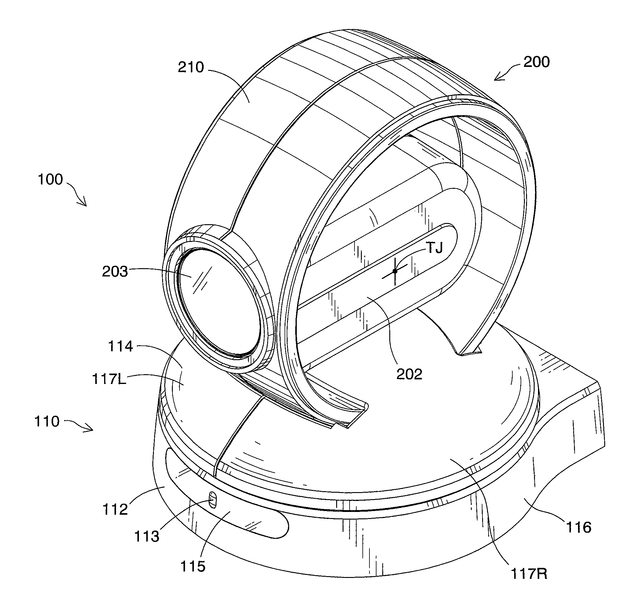
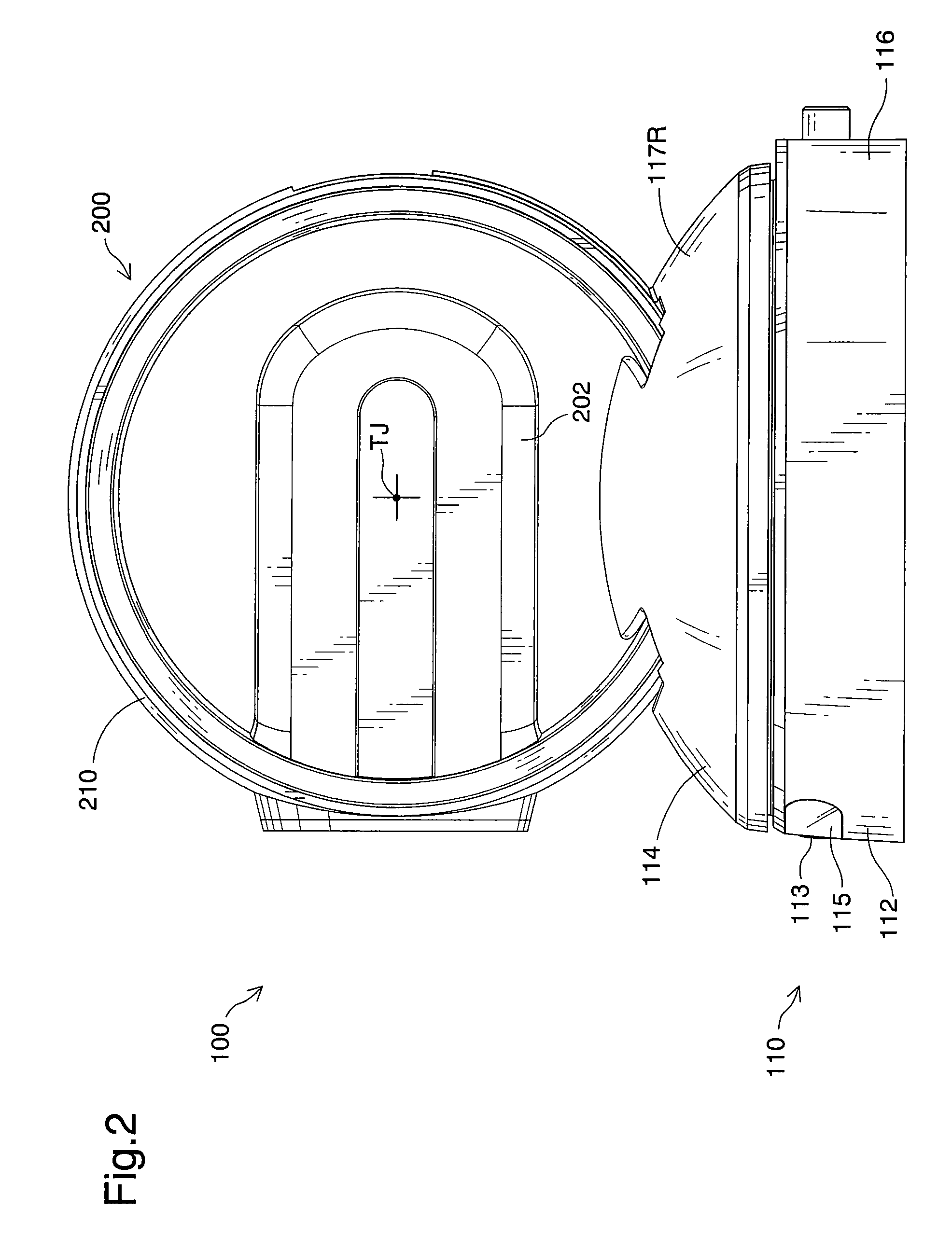
[0044]One mode of carrying out the invention is described below as a preferred embodiment with reference to the accompanied drawings. The description first regards the general overview and the operations of an imaging apparatus 100 as an application of a security camera in one embodiment of the invention. FIG. 1 is a perspective view showing an imaging apparatus 100 as application of a security camera in one embodiment of the invention. FIG. 2 is a side view showing the imaging apparatus 100 of the embodiment. FIG. 3 is a perspective view showing a camera assembly 200 of the imaging apparatus 100 tilted to an upper-most end in a vertical movable range. FIG. 4 is a perspective view showing the camera assembly 200 tilted to a lower-most end in the vertical movable range. FIG. 5 is a perspective view showing the camera assembly 200 panned to one further-most end in a horizontal movable range. FIG. 6 is a perspective view showing the camera assembly 200 panned to the other further-most ...


PUM


Abstract

In the imaging apparatus of the invention, a camera assembly 200 including a camera 202 is mounted on and supported by a base 110 in a pivotally rotatable manner both in a vertical direction and in a horizontal direction to allow tilting motions and panning motions of the camera 202. The camera assembly 200 is supported on an assembly fixation structure 114 of the base 110 to allow the tilting motions of the camera assembly 200. The assembly fixation structure 114 is panned relative to a base foot 112 of the base 110. A panning rotation gear 175 for the panning motions of the camera 202 is fixed on a ground plate 121, which has a positional change relative to a pedestal plate unit 130 in the assembly fixation structure 114. A tilting motor 160, a panning motor 162, and relevant vertical and horizontal rotation transmission mechanisms required for the tilting motions and the panning motions of the camera 202 are collectively arranged on the pedestal plate unit 130 of the assembly fixation structure 114. The tilting motor 160 and the panning motor 162 are arranged in an attitude having respective output shafts in the horizontal direction and are disposed to face each other across a pivot shaft fitting element 135 on the pedestal plate unit 130. This arrangement of the invention enables further downsizing of the whole imaging apparatus applied to, for example, a security camera.

Description

CROSS-REFERENCE TO RELATED APPLICATION[0001]The present application claims the priority based on Japanese Patent Application No. 2006-190184 filed on Jul. 11, 2006, the disclosure of which is hereby incorporated by reference in its entirety.BACKGROUND OF THE INVENTION[0002]1. Field of the Invention[0003]The present invention relates to an imaging apparatus equipped with a camera rotatable both in a vertical direction and in a horizontal direction.[0004]2. Description of the Related Art[0005]Imaging apparatuses have diversity of applications and are used, for example, as security cameras in various locations including banks, railway stations, supermarkets, convenience stores, and video game arcades.[0006]Security camera devices are generally designed to allow pivotal rotations of a camera in a horizontal direction (hereafter also referred to as panning motions), as well as pivotal rotations of the camera in a vertical direction (hereafter also referred to as tilting motions), with a ...

Claims


Application Information

Patent Timeline
IPC IPC(8): G03B17/00
CPCF16M11/10F16M11/12H04N5/2251F16M11/2014F16M11/18H04N23/50H04N23/695
Inventor YAMANE, AKIRASUGIYAMA, EIJI
Owner ELMO CO LTD
Features
  • Generate Ideas
  • Intellectual Property
  • Life Sciences
  • Materials
  • Tech Scout
  • Unparalleled Data Quality
  • Higher Quality Content
  • 60% Fewer Hallucinations
Learn More