Anchoring drill bit, system and method of anchoring

a technology of anchoring drill bit and drill bit, which is applied in the direction of drilling/boring measurement device, twisting drill, turning machine accessories, etc., can solve the problems of damage to the surface of the concrete, etc., and achieve the effect of low cos

a technology of anchoring drill bit and drill bit, which is applied in the direction of drilling/boring measurement device, twisting drill, turning machine accessories, etc., can solve the problems of damage to the surface of the concrete, etc., and achieve the effect of low cos

US20080014048A1Inactive Publication Date: 2008-01-17NADLER DONALD S

Image

  • Anchoring drill bit, system and method of anchoring
  • Anchoring drill bit, system and method of anchoring
  • Anchoring drill bit, system and method of anchoring

Examples


Embodiment Construction

[0026] As required, a detailed embodiment of the present inventions is disclosed herein; however, it is to be understood that the disclosed embodiment is merely exemplary of the principles of the invention, which may be embodied in various forms. Therefore, specific structural and functional details disclosed herein are not to be interpreted as limiting, but merely as a basis for the claims and as a representative basis for teaching one skilled in the art to variously employ the present invention in virtually any appropriately detailed structure.

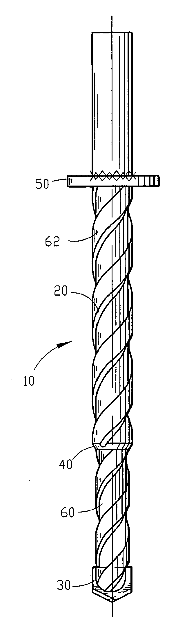
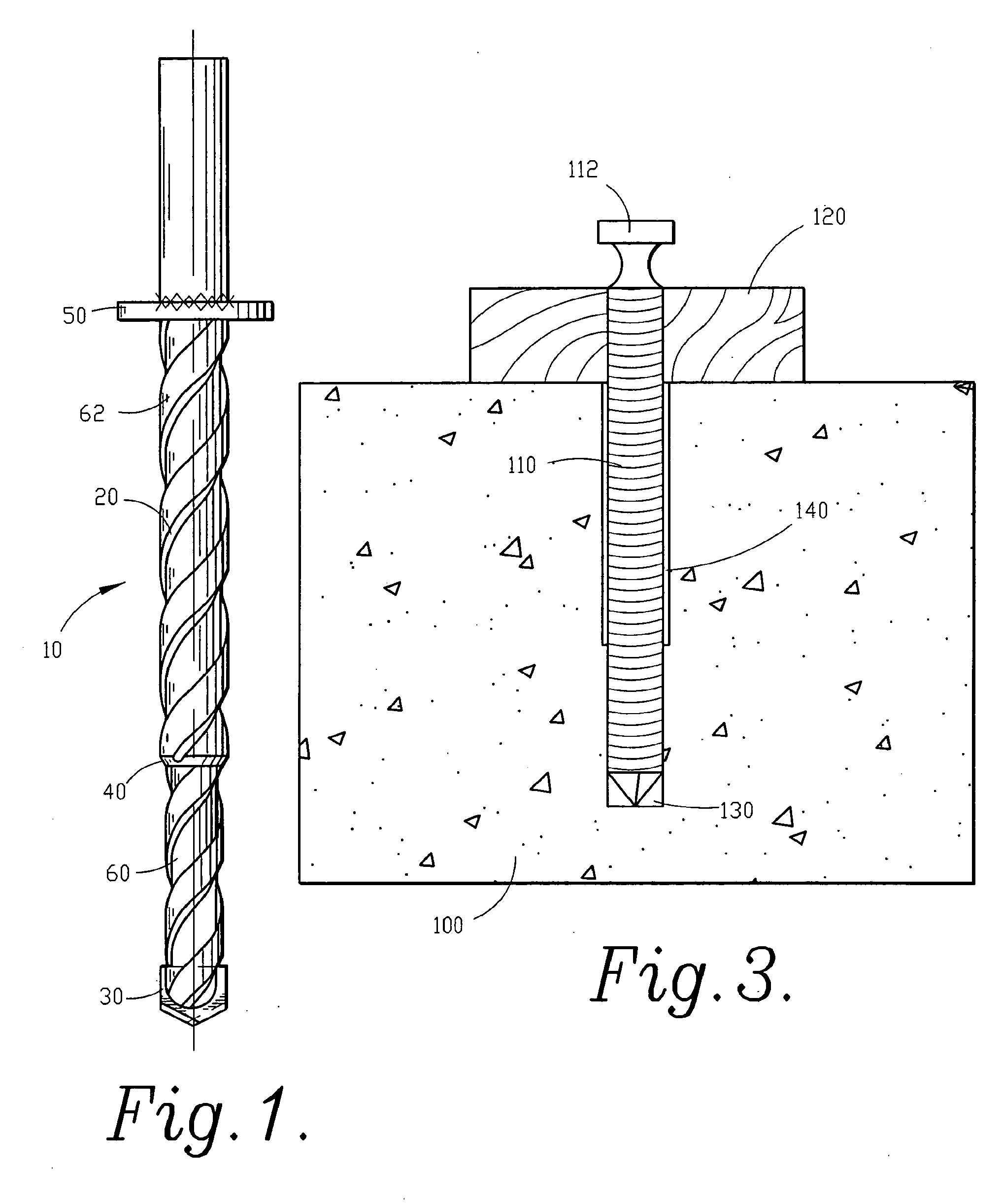
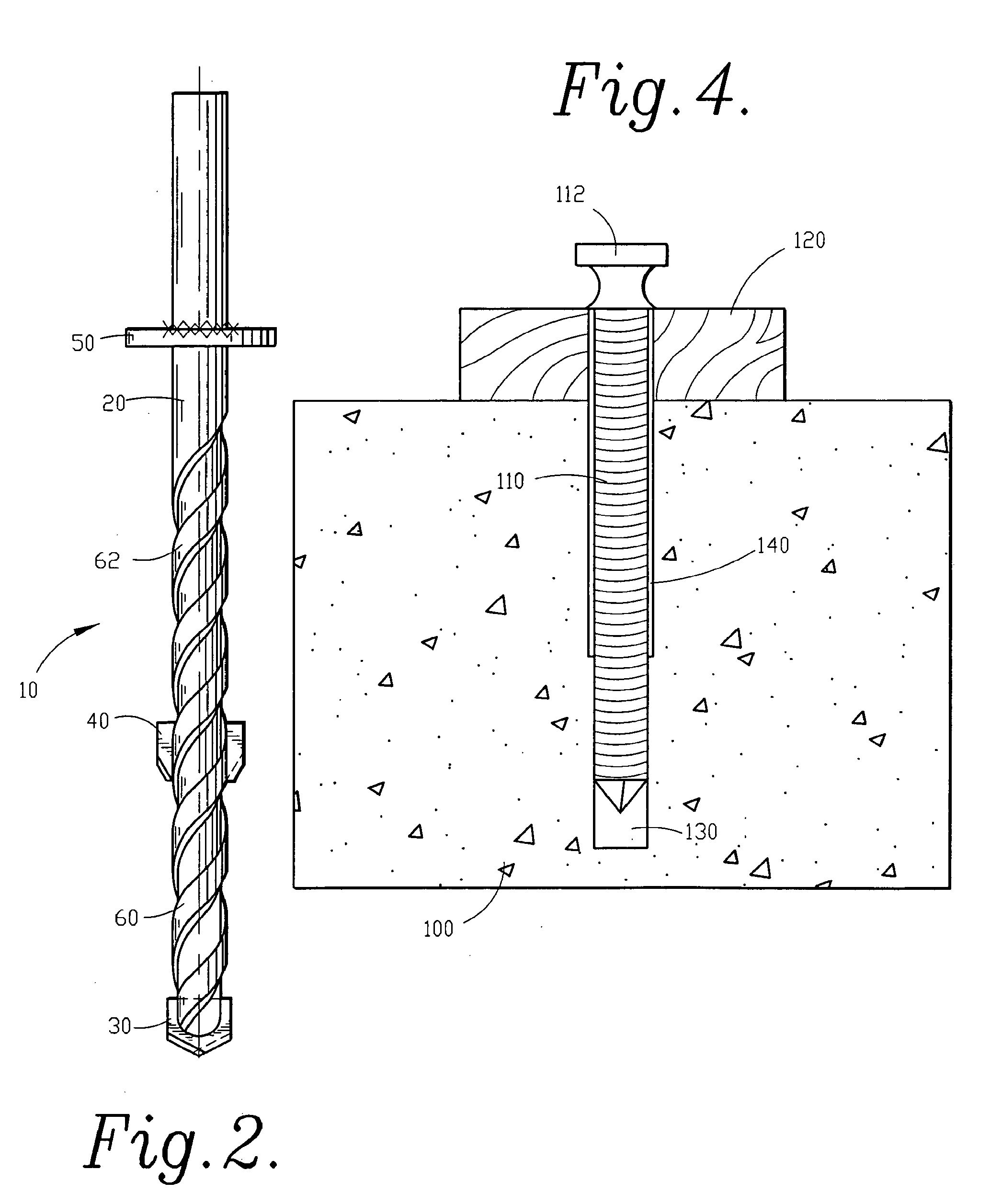
[0027] Referring to FIG. 1 a front sectional view of one embodiment of a two-stage drill bit of the instant invention is shown in which drill bit 10 includes shank / shaft 20, first stage cutter 30 on shaft 20, second stage cutter 40 on shaft 20 spaced apart from first stage cutter 30, and depth gage 50 on shaft 20 spaced apart from second stage cutter 40 in a direction opposite first stage cutter 30. As is shown in FIG. 1, first stage cutter...


PUM

PropertyMeasurementUnit
diameteraaaaaaaaaa
diameteraaaaaaaaaa
diameteraaaaaaaaaa

Abstract

A system, apparatuses and methods for anchoring are provided. The system includes two-stage drill bit and a method of anchoring into a two-stage hole drilled by the drill bit. The apparatus of the instant invention includes a two-stage drill bit for drilling a pilot hole for a common nail into a material such as concrete, stone, masonry or cementuous or other materials. The method of the instant invention includes the steps of drilling a first hole within a material to which an object is to be anchored, drilling a second hole concentric with the first hole, and placing an anchor within the holes.

Description

[0001] This application is a divisional of U.S. application Ser. No. 10 / 988,998 filed Nov. 12, 2004, which claims priority pursuant to 35 U.S.C. 119(e) to co-pending U.S. Provisional Patent Application Ser. No. 60 / 519,223, filed Nov. 12, 2003, the entire disclosures of which are incorporated herein by reference.FIELD OF THE INVENTION [0002] The present invention relates generally to systems, apparatuses and methods for anchoring. More particularly, the present invention is concerned with a two-stage drill bit and a method for anchoring into brittle materials such as concrete, stone, masonry and cementuous materials using a common nail. BACKGROUND OF THE INVENTION [0003] In construction applications it is often necessary or desirable to anchor into an existing concrete structure. In many construction applications the anchor is intended to be permanent to tie in a newer structure with an existing concrete structure. In such permanent anchoring applications, removal of the anchors is g...

Claims


Application Information

Patent Timeline
17 Jan 2008
Publication
US20080014048A1
IPC
F16B25/10; B23B49/00; B23B51/00; B23B51/02; E21B10/44
CPC
B23B2251/204; B23B2251/50; B23B2251/54; B23B2260/0485; B23B2270/54; B23B49/005; Y10T408/8925; B23B51/02
Inventors
NADLER, DONALD S.