Method And Apparatus For Treatment Of Cardiac Valves

a technology for cardiac valves and pulmonary valves, applied in the field of cardiac valve disease treatment, can solve problems that are not available to all, and achieve the effect of improving seals and avoiding constricting flow within the adapter

Inactive Publication Date: 2008-01-17
MEDTRONIC INC
View PDF99 Cites 263 Cited by
  • Summary
  • Abstract
  • Description
  • Claims
  • Application Information

AI Technical Summary

Benefits of technology

[0012] The material from which the adapter is made is not especially limited. However, it is particularly preferred that the material is flexible in order that it can form to the shape of the vessel within which is it implanted. This allows for a better seal with the vessel walls and also allows the device to flex with the vessel as it moves naturally within the body. It is also preferred that the outer portion of the adapter can be compressed to a certain degree, without significant compression of the inner portion. This allows the adapter to be subjected to normal stress and strain in the body, without constricting flow within the adapter. The flexible materials discussed herein are suitable for achieving this.

Problems solved by technology

While the approach to pulmonary valve replacement described in the above patent applications and articles appears to be a viable treatment, it is not available to all who might benefit from it due to the relatively narrow size range of available valved segments of bovine jugular veins.
Unfortunately, the most common groups of patients requiring pulmonary valve replacement are adults and children who underwent transannular patch repair of tetralogy of Fallot during infancy.

Method used


Image

  • Method And Apparatus For Treatment Of Cardiac Valves
  • Method And Apparatus For Treatment Of Cardiac Valves
  • Method And Apparatus For Treatment Of Cardiac Valves

Examples


first embodiment

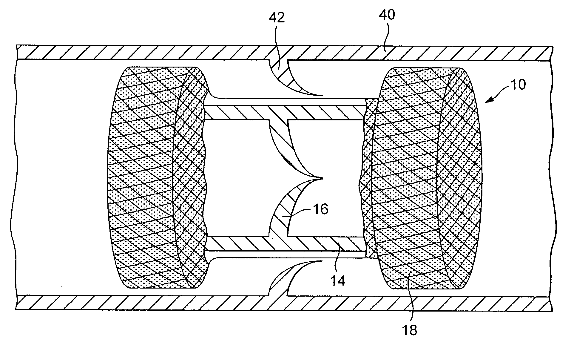
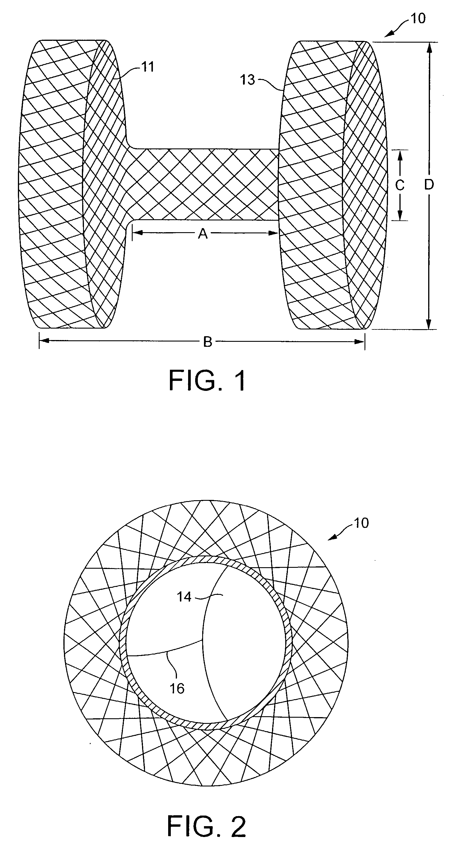
[0036]FIG. 2 is an end view of the adapter stent 10 of FIG. 1, with a valved venous segment 14 installed, illustrating a replacement valve according to the present invention. Leaflets 16 are visible. The venous segment is sutured to the adapter stent along its proximal and distal edges and preferably is sutured to the stent at most, if not all of the intersections of the wire of the stent which overlie the venous segment. Additional sutures may be employed in the areas between the commissures of the valve. For example, an example of the assembly of suitable valve components is described in more detail in co-pending U.S. Provisional Application, Attorney No. P-0022027.00 filed Nov. 19, 2004.

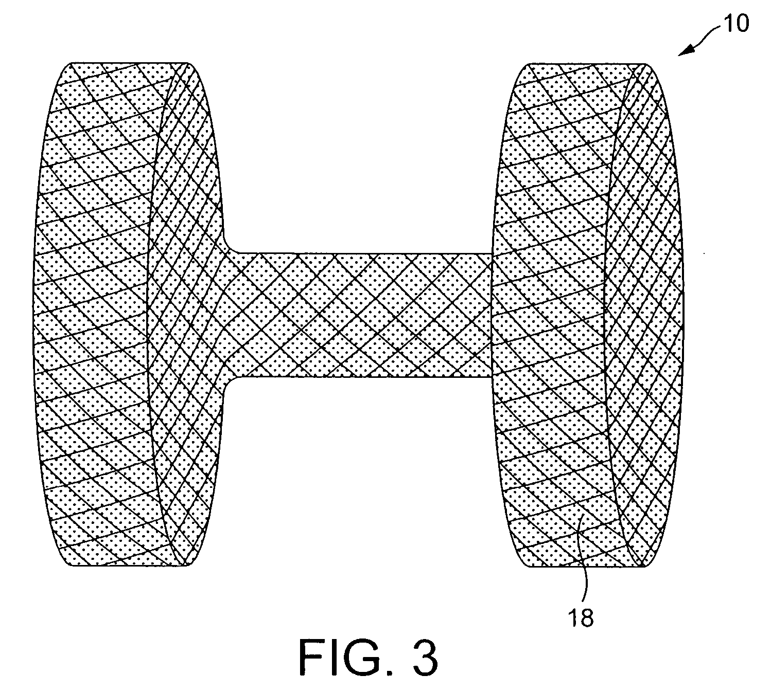
[0037]FIG. 3 illustrates the adapter stent of FIG. 1 with a liquid resistant covering 18 applied. This covering may be a 0.3 mm ePTFE membrane of the type presently used to produce covered stents, supplied by Zeus Inc., Orangeburg, S.C. Alternative coverings such as silicone rubber, polyurethane, ...

second embodiment

[0042]FIG. 7 illustrates a stented valved venous segment 50 which may be used in conjunction with the invention. The stented venous segment 50 may correspond to that described in the above-cited Tower, et al., and Bonhoeffer et al. references. The stented venous segment is expandable to an outer diameter as large as the inner diameter of middle portion of the adapter stent. The stent 52 may be fabricated of platinum, stainless steel or other biocompatible metal. While it may be fabricated using wire stock as described in the above-cited Tower, et al. applications, it is believed that a more likely commercial embodiment would be produced by machining the stent from a metal tube, as more commonly employed in the manufacture of stents. The specifics of the stent are not critical to the invention, and any known generally cylindrical stent configuration is probably workable. The venous segment 54 is mounted within the stent 52 with its included valve located between the ends of the stent...


PUM


Abstract

Provided is a method and apparatus for placing a valve (14) in a tubular organ having a greater diameter than the valve, comprising: an expandable tubular adapter (10) having an outer portion with a diameter suitable for contacting the inner walls of the tubular organ, and an inner portion with a diameter suitable for placement of the valve; a valve mounted within the inner portion of the adapter; and a system for placing a valved vascular segment in a tubular organ having a greater inner diameter than the outer diameter of the vascular segment, comprising: an expandable tubular adapter having an outer portion with a diameter suitable for contacting the inner walls of the tubular organ, and an inner portion with a diameter suitable for placement of the valve; an expandable valved vascular segment, expandable to the diameter of the inner portion of the adapter.

Description

FIELD OF THE INVENTION [0001] This invention relates generally to treatment of cardiac valve disease and more particularly to replacement of malfunctioning pulmonary valves. BACKGROUND OF THE INVENTION [0002] Recently, there has been interest in minimally invasive and percutaneous replacement of cardiac valves. In the specific context of pulmonary valve replacement, US Patent Application Publication Nos. 2003 / 0199971 A1 and 2003 / 0199963 A1, both filed by Tower, et al. and incorporated herein by reference describe a valved segment of bovine jugular vein, mounted within an expandable stent, for use as a replacement pulmonary valve. The replacement valve is mounted on a balloon catheter and delivered percutaneously via the vascular system to the location of the failed pulmonary valve and expanded by the balloon to compress the native valve leaflets against the right ventricular outflow tract, anchoring and sealing the replacement valve. As described in the articles: “Percutaneous Inser...

Claims


Application Information

Patent Timeline
Patent Type & Authority Applications(United States)
IPC IPC(8): A61F2/06
CPCA61F2/2409A61F2230/0078A61F2/2475A61F2/2418
Inventor BONHOEFFER, PHILIPP
Owner MEDTRONIC INC
Why Eureka
Try Eureka