Substrate laminating apparatus

a laminating apparatus and substrate technology, applied in the direction of auxillary welding devices, soldering apparatus, instruments, etc., can solve the problems of dust generation or damage, and achieve the effect of reducing atmospheric pressure and high accuracy

Inactive Publication Date: 2008-01-24
HITACHI LTD
View PDF4 Cites 5 Cited by
  • Summary
  • Abstract
  • Description
  • Claims
  • Application Information

AI Technical Summary

Benefits of technology

[0009] In the substrate laminating apparatus according to the present invention, an upper substrate is picked up and held on the upper table reliably in medium vacuum and evacuation time to decrease the pressure from atmospheric pressure to high vacuum, which accounts for the largest percentage of laminating time, is shortened and lamination of substrates is carried out in vacuum with high accuracy.

Problems solved by technology

The above conventional technique causes the following bottleneck in efforts to increase productivity: it takes time to change the pressure level in the vacuum chamber from atmospheric to vacuum in order to make the preliminary chamber and the vacuum chamber have the same atmosphere when a substrate is carried in or out.
In the technique disclosed by Japanese Patent Application Laid-open Publication No. 2001-305563, since substrates are placed on rollers for transportation, they may be damaged or generate dust due to a friction caused by their movement on the rollers.

Method used


Image

  • Substrate laminating apparatus
  • Substrate laminating apparatus
  • Substrate laminating apparatus

Examples


Embodiment Construction

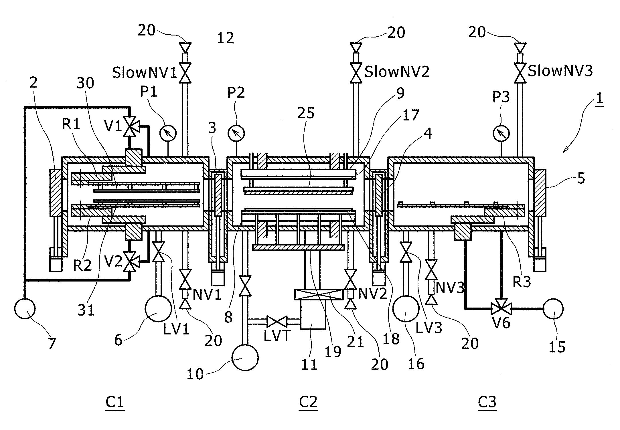
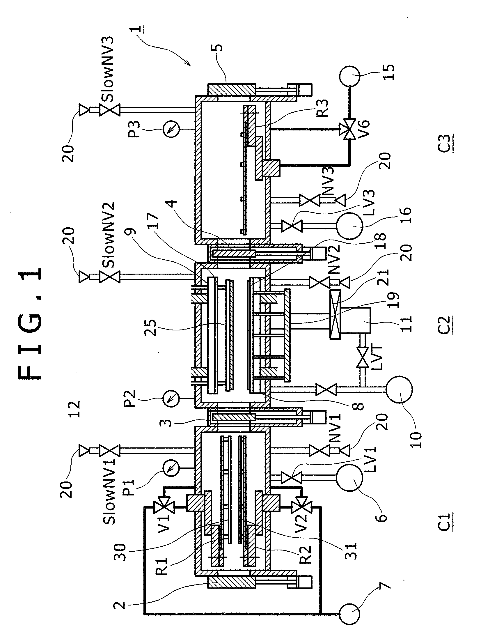
[0016] Next, a preferred embodiment of the present invention will be described referring to the accompanying drawings. As shown in FIG. 1, a substrate laminating apparatus according to the present invention includes: a first chamber C1 into which an upper and a lower substrate are carried with sealant applied to either substrate and liquid crystal dropped on the lower substrate (sometimes called the substrate pre-treatment chamber or substrate input chamber); a second chamber C2 which serves as a vacuum laminating chamber where an upper and a lower substrate are stuck together; and a third chamber C3 (sometimes called the substrate post-treatment chamber or substrate delivery chamber) which delivers a substrate laminate (liquid crystal panel). In the first chamber C1, there are an upper substrate carrying robot hand R1 for carrying in an upper substrate 30 and a lower substrate carrying robot hand R2 for carrying in a lower substrate 31. In the third chamber C3, there is a delivery ...


PUM

PropertyMeasurementUnit
suction/adsorptionaaaaaaaaaa
atmospheric pressureaaaaaaaaaa
pressuresaaaaaaaaaa

Abstract

A substrate laminating apparatus which sticks substrates together in vacuum with high accuracy. The apparatus includes a first chamber into which two substrates are carried; a second chamber in which substrates are stuck together; and a third chamber which delivers a substrate laminate. The pressure level in the first chamber and the third chamber is varied from atmospheric to medium vacuum under control and that in the second chamber is varied from medium vacuum to high vacuum under control. In the second chamber, electrostatic adsorption means which can move up and down picks up an upper substrate and holds it on an upper table.

Description

BACKGROUND OF THE INVENTION [0001] (1) Field of the Invention [0002] The present invention relates to a substrate laminating apparatus and more particularly to a substrate laminating apparatus suitable for assembling a liquid crystal display panel in which substrates to be laminated are held in a vacuum chamber facing each other and laminated with a narrow spacing between them. [0003] (2) Description of the Related Art [0004] The manufacture of liquid crystal display panels includes a process in which two glass substrates with transparent electrodes and thin-film transistor arrays are stuck together with a very small spacing of several micrometers or so between them using an adhesive agent (hereinafter sometimes called sealant) put on a substrate peripheral area (a finished substrate laminate will be hereinafter called a cell) and liquid crystal is sealed into the space thus made. [0005] One existing technique of sealing liquid crystal in this process is as follows: liquid crystal i...

Claims


Application Information

Patent Timeline
Patent Type & Authority Applications(United States)
IPC IPC(8): B32B37/00
CPCB32B38/18B32B2038/1891B32B2309/68Y10T156/17G02F1/1303G02F1/1333B32B2457/20G02F1/13
Inventor MITSUMOTO, MASARUWATANABE, SHIGEOKUNIHIRO, TATSUHITO
Owner HITACHI LTD
Why Eureka
Try Eureka