Axle-driven generator for railway carriages and the like

a technology of axle-driven generators and carriages, which is applied in the direction of dynamo-electric machines, electrical apparatus, climate sustainability, etc., can solve the problems of low torque transmission, large diameter, and construction problems of axle-driven generators, and achieve the effect of eliminating complex transmission means

Inactive Publication Date: 2008-01-24
LANDERT MOTOREN
View PDF7 Cites 20 Cited by
  • Summary
  • Abstract
  • Description
  • Claims
  • Application Information

AI Technical Summary

Benefits of technology

[0025] In the past, continuous, non-separated axle-driven generators have been used; this had the drawback that the generators either had to be flanged at their end face on the wheelset shaft or they had to be arranged on the bogie

Problems solved by technology

However, the end face of the axle-driven generator is flanged directly onto the axle bearing, and this has major drawbacks.
The first drawback is that the end-face installation space pointing in the axial direction is markedly delimited at the axle bearing, thus preventing a large generator with a corresponding power output from being mounted at this location.
A further drawback is that the guiding of the axle, which has a relatively

Method used


Image

  • Axle-driven generator for railway carriages and the like
  • Axle-driven generator for railway carriages and the like
  • Axle-driven generator for railway carriages and the like

Examples


Embodiment Construction

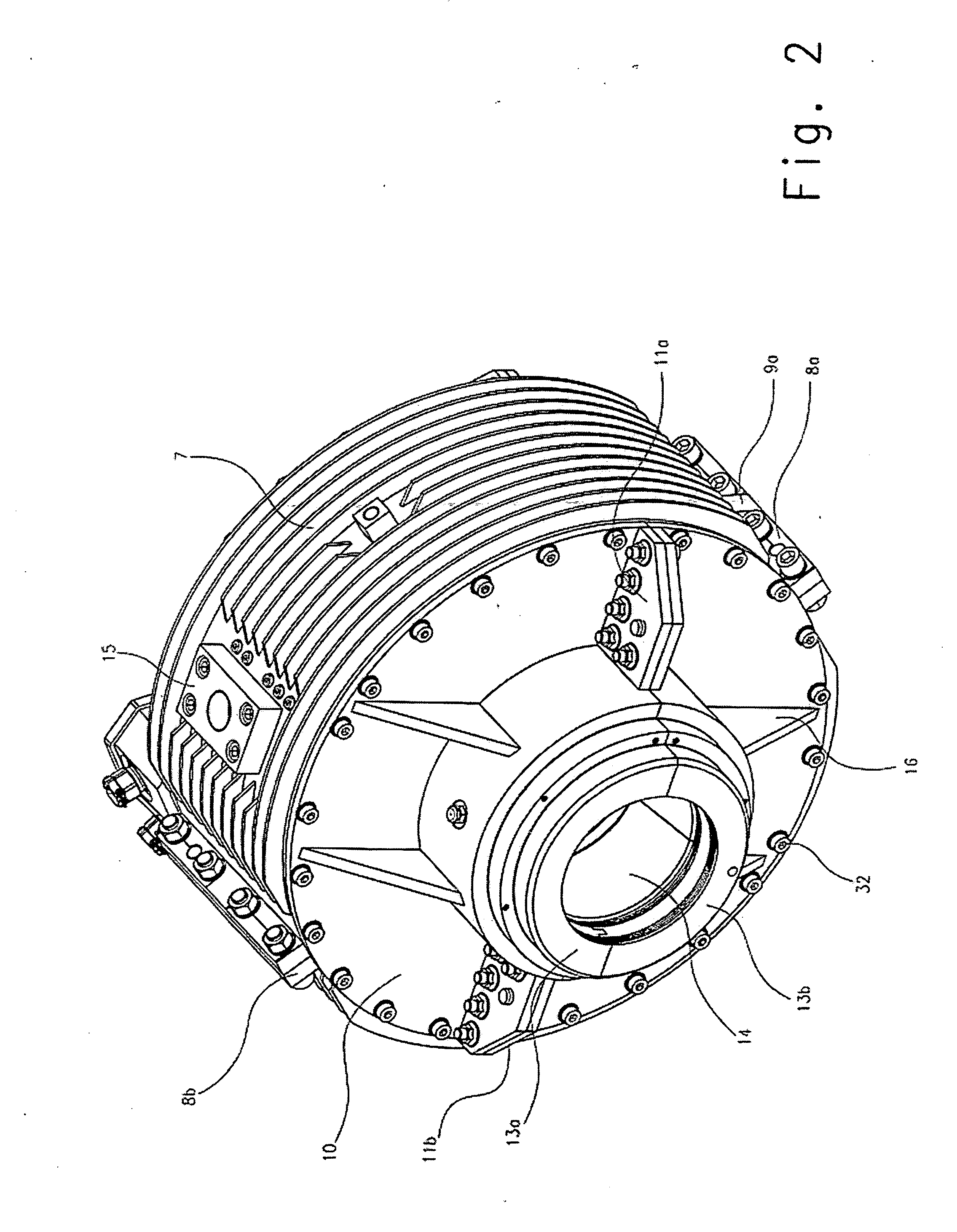
[0066] The stator housing 7 is of two-part construction and consists of an upper and a lower ring half, the two ring halves being joined together by connecting flanges 8a, 8b.

[0067] A receptacle 15 for attachment of the torque bracket illustrated in FIG. 7 is shown to be rotationally engaged with the outer circumference of the upper stator housing 7.

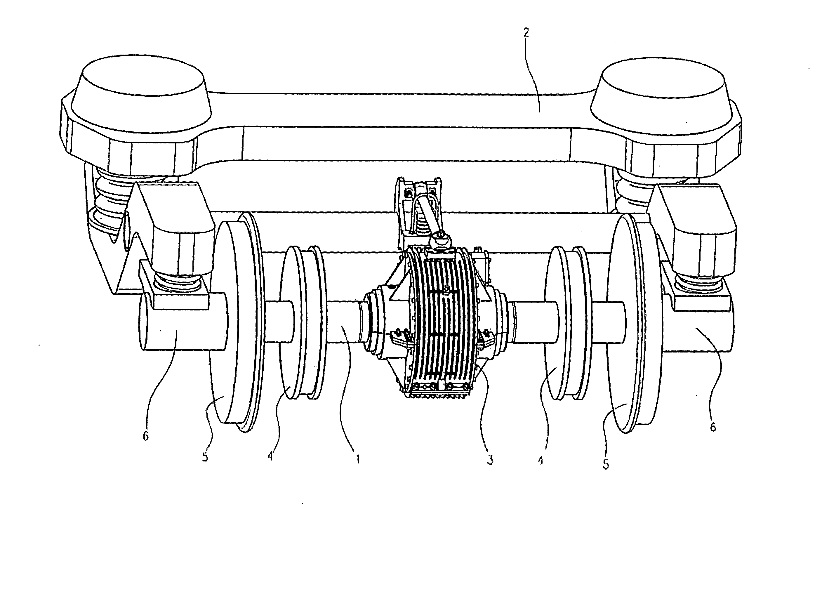
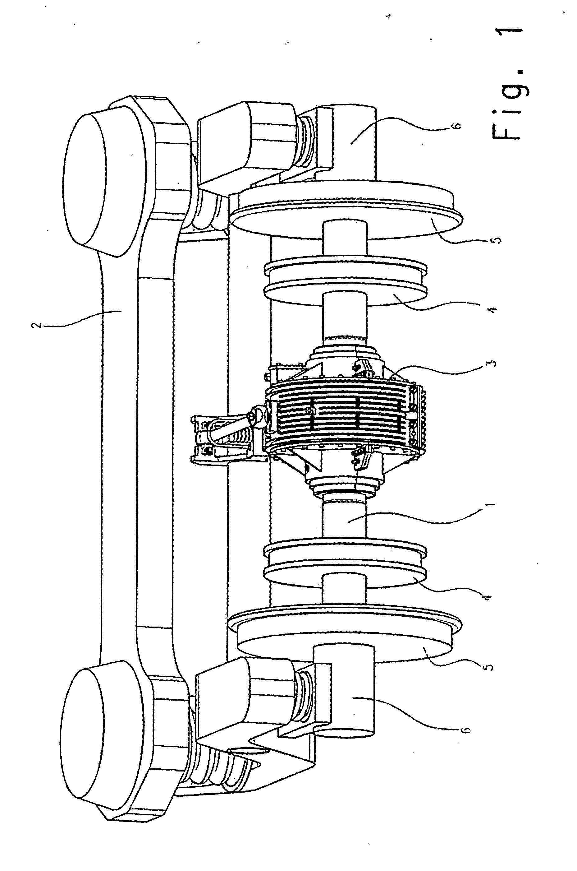
[0068]FIG. 2 shows that the wheelset shaft 1 passes through the shaft hole 14 in the rotor and is rotationally engaged with the rotor, a bearing shell 13, which is also separated and is formed from the bearing shell halves 13a, 13b, being visible.

[0069]FIG. 2 also shows the end-face bearing shield 10 which is screwed to the stator housing 7 using screw connections 32.

[0070] The bearing shield 10 is flanged to the bearing shell 13 using reinforcement ribs 16.

[0071] The opposing connecting flanges 11 shown in the drawing are also separated and consist of the connecting flanges 11a, 11b which are screwed together.

[0072] The two bearin...


PUM


Abstract

Axle-driven generator for railway carriages and the like, consisting of at least one axle-driven generator, the rotor of which is rotationally engaged with the wheelset shaft and the stator housing of which is secured to the housing. In order to support a large, powerful axle-driven generator, it is provided that the axle-driven generator is placed between the wheel discs directly on the wheelset shaft and said wheelset shaft passes through the axle-driven generator.

Description

BACKGROUND OF THE INVENTION [0001] 1. Field of the Invention [0002] The invention relates to an axle-driven generator for railway carriages according to the preamble of claim 1. The term “railway carriage” refers to all rail-bound, non-self-driven vehicles. [0003] 2. Description of the Prior Art [0004] EP 1 033 296 A2 discloses an axle-driven generator which is flanged directly on the axle. However, the end face of the axle-driven generator is flanged directly onto the axle bearing, and this has major drawbacks. The first drawback is that the end-face installation space pointing in the axial direction is markedly delimited at the axle bearing, thus preventing a large generator with a corresponding power output from being mounted at this location. The axle-driven generator is therefore able to protrude beyond the outer end face of the wheelset shaft only by a limited length. [0005] A further drawback is that the guiding of the axle, which has a relatively large diameter, through the ...

Claims


Application Information

Patent Timeline
IPC IPC(8): B61D43/00H02K7/18
CPCB61D43/00H02K5/00Y02T30/36H02K7/12H02K7/1846H02K7/108Y02T30/00
Inventor ROTH, KURT
Owner LANDERT MOTOREN
Why Eureka
Try Eureka