Ultra low power charging implant sensors with wireless interface for patient monitoring

a low-power, implant-based technology, applied in the field of intraocular pressure monitoring devices and methods, can solve the problems of low power requirements that may not necessitate any particular alignment, damage to delicate structures, and the risk of affecting vision significantly or the associated liability, so as to improve the versatility and reprogramming/updating, improve the effect of power management and improve the treatment

Inactive Publication Date: 2016-03-03
INJECTSENSE INC
View PDF33 Cites 39 Cited by
  • Summary
  • Abstract
  • Description
  • Claims
  • Application Information

AI Technical Summary

Benefits of technology

[0011]The invention provides devices and methods for obtaining IOP measurements within an eye of a patient multiple times a day with a miniature sensor device implanted within an eye and wirelessly charging the sensor device and communicating the IOP measurements to an external device or server for monitoring and / or trending of IOP measurements for improved glaucoma treatments. In one aspect, the invention provides a sensor device that measures and stores IOP data with ultra low power consumption such that the IOP measurements can be obtained more frequently, up to hourly sampling, and stored over a time increment of at least one week on a single charge of the miniature device, the single charge being performed in a relatively short duration of time, such as about three hours or less, typically between about 20 minutes and 2 hours depending on the number of charging cycles experienced by the device over its lifetime. In some embodiments, the sensor device includes a microcontroller that allows the sensor device to switch between differing use modes, allows for improved versatility and reprogramming / updating, as well as improved power management. For example, in some embodiments, the sensor device uses a microcontroller to power the sensor device functions with a high impedance thin-film battery by switching between the battery and a supercapacitor which decouples the battery from an ASIC of the device so as to perform impedance conversion. Such configurations allow for improved power management and increased functionality.

Problems solved by technology

Further, such ultra-low power requirements may not necessitate any particular alignment (e.g. rotational alignment) between the implantable sensor device and the external charger unless the recharging period is above the upper bound of 15 seconds (due to low power transfer efficiency or the limited allowable tissue exposure to the AC magnetic fields).
Because the anterior chamber is a particularly sensitive region, great care must be taken to avoid contacting the various parts of the anterior chambers, which may result in damage to the delicate structures therein.
As discussed above, monitoring the anterior chamber directly is not worth the risk of affecting vision significantly or the associated liability.

Method used


Image

  • Ultra low power charging implant sensors with wireless interface for patient monitoring
  • Ultra low power charging implant sensors with wireless interface for patient monitoring
  • Ultra low power charging implant sensors with wireless interface for patient monitoring

Examples


Embodiment Construction

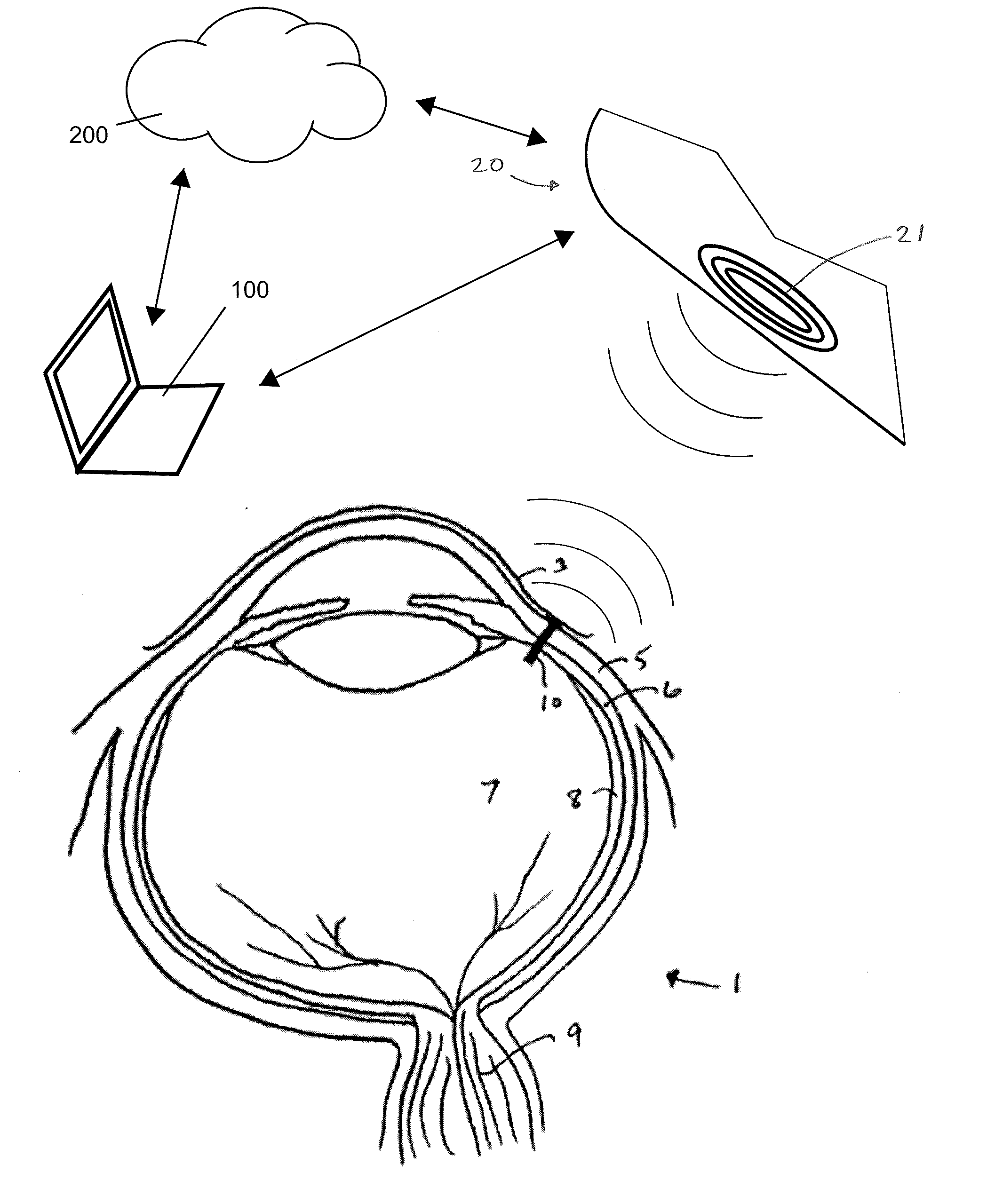
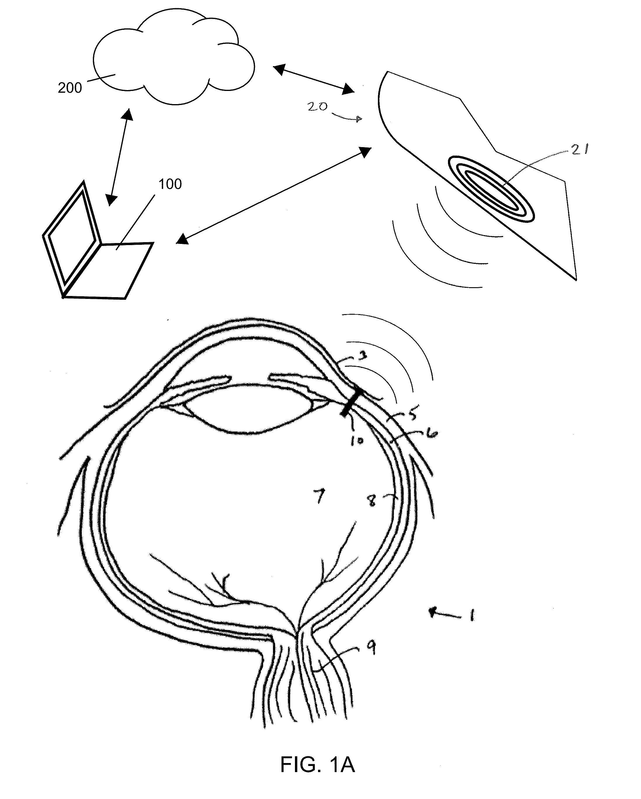
[0037]FIG. 1A is an overview illustration of a miniature sensor device 10 implanted within an eye 1 in wireless communication with an external portable device 20 held in close proximity to the eye for charging and / or data transmission. While implanted within the eye, the miniature sensor device 10 obtains multiple pressure measurements over a given time increment according to a sampling program stored on a memory of the sensor device 10 and stores pressure measurement information corresponding to the multiple pressure measurements on the memory of the device powered by energy stored in an energy storage component of the sensor device 10. Upon detection of a coil of an external data acquisition / charging device held in close proximity to the eye having an implanted sensor device, a charging and / or telemetry sequence is initiated in which one or more coils of the sensor device 10 wirelessly couple with one or more corresponding coils 21 of the external device 20 and transmit energy to ...


PUM


Abstract

Methods and devices for monitoring intra-ocular pressure of a patient using a miniature implantable sensor device are provided herein. Methods include obtaining multiple pressure measurements each day during an increment of an extended monitoring period according to a sampling program and wirelessly transmitting stored measurement data and wirelessly charging the device. Measurements and data process is performed with low power requirements such that sampling can be performed hourly for at least one week using energy stored on the miniature device and measurement data can be transmitted and the device charged rapidly when an external portable data acquisition/charging device is held in proximity to the device. In one aspect, methods include switching between differing use modes and powering the sampling device with a high impedance battery by switching between a supercapacitor and the battery with a microcontroller to perform impedance conversion.

Description

CROSS-REFERENCES TO RELATED APPLICATIONS[0001]The present application claims the benefit of priority of U.S. Provisional Patent Application Nos. 62 / 019,826 filed Jul. 1, 2014; 62 / 019,841 filed Jul. 1, 2014; and 62 / 044,895 filed Sep. 2, 2014; each of which is incorporated herein by reference in its entirety.[0002]The present application is related to the following co-assigned applications: U.S. Provisional Patent Application Ser. No. 62 / 019,826 (Attorney Docket No. 96933-000100US) entitled “Methods and Devices for Implantation of Intraocular Pressure Sensors” filed on Jul. 1, 2014, U.S. Provisional Patent Application Ser. No. 62 / 019,841 (Attorney Docket No. 96933-000200US) entitled “Hermetically Sealed Implant Sensors with Vertical Stacking Architecture” filed on Jul. 1, 2014, concurrently filed U.S. Non-Provisional patent application Ser. No. 14 / 789,491 (Attorney Docket No. 96933-000110US-947259), and concurrently filed U.S. Non-Provisional patent application Ser. No. ______ (Attorn...

Claims


Application Information

Patent Timeline
Patent Type & Authority Applications(United States)
IPC IPC(8): A61B5/07A61B3/00A61B3/16A61B5/00
CPCA61B5/746A61B5/7282A61B5/4836A61B3/16A61B3/0025A61B2562/085A61B2560/0219A61B5/076A61B5/686A61B5/6867A61B5/0004A61B5/0002
Inventor CAO, ARIEL
Owner INJECTSENSE INC
Why Eureka
Try Eureka