Liquid crystal display device, driving control circuit and driving method used in same

a technology of liquid crystal display and control circuit, which is applied in the direction of instruments, static indicating devices, etc., can solve the problems of flicker, greater flicker, and the ability to reduce the blur of moving images caused by the response of liquid crystal and the holding-type driving method, so as to reduce the flicker

Active Publication Date: 2008-01-24
NEC LCD TECH CORP
View PDF13 Cites 27 Cited by
  • Summary
  • Abstract
  • Description
  • Claims
  • Application Information

AI Technical Summary

Benefits of technology

[0029] With the above configurations, each frame of an input video signal to be input at a specified frequency is divided into M-pieces of sub-frames each having a sub-frame frequency being M (M is an integer being 4 or more) times as large as the specified frame frequency and an overdriving operation is performed on each of pixel regions in the first frame during one frame period and a normal driving operation is performed during one frame in the second and thereafter and a backlight flashes N (N is an integer being 2 or more) times at specified time inte...

Problems solved by technology

However, the above conventional liquid crystal display device has the following problem.
That is, the problem arises that, though, in the conventional technology, combination of the overdriving and impulse driving methods improves quality of moving images, a flicker occurs when the black insertion method or backlight blinking method are performed in a region having many images standing still on a display screen at a normal frame frequency (60 Hz).
When an LED is used as a backlight source, a response of the LED in its turning-on to its turning-off states or vice versa is more rapid than that of a CRT and, therefore, quality of moving images by using the backlight blinking is greatly improved, however, a greater flicker occurs.
Also, another problem...

Method used


Image

  • Liquid crystal display device, driving control circuit and driving method used in same
  • Liquid crystal display device, driving control circuit and driving method used in same
  • Liquid crystal display device, driving control circuit and driving method used in same

Examples


first embodiment

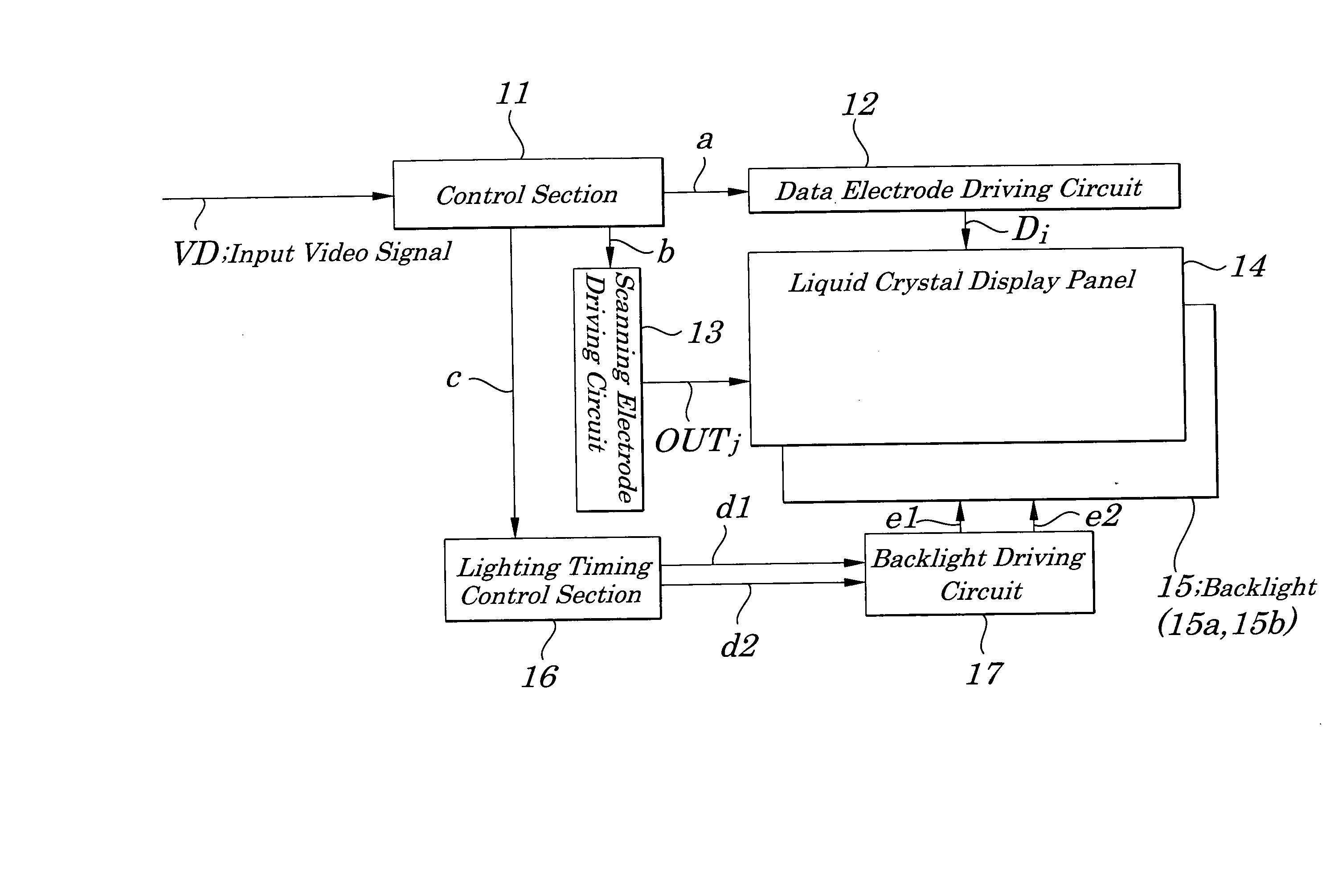
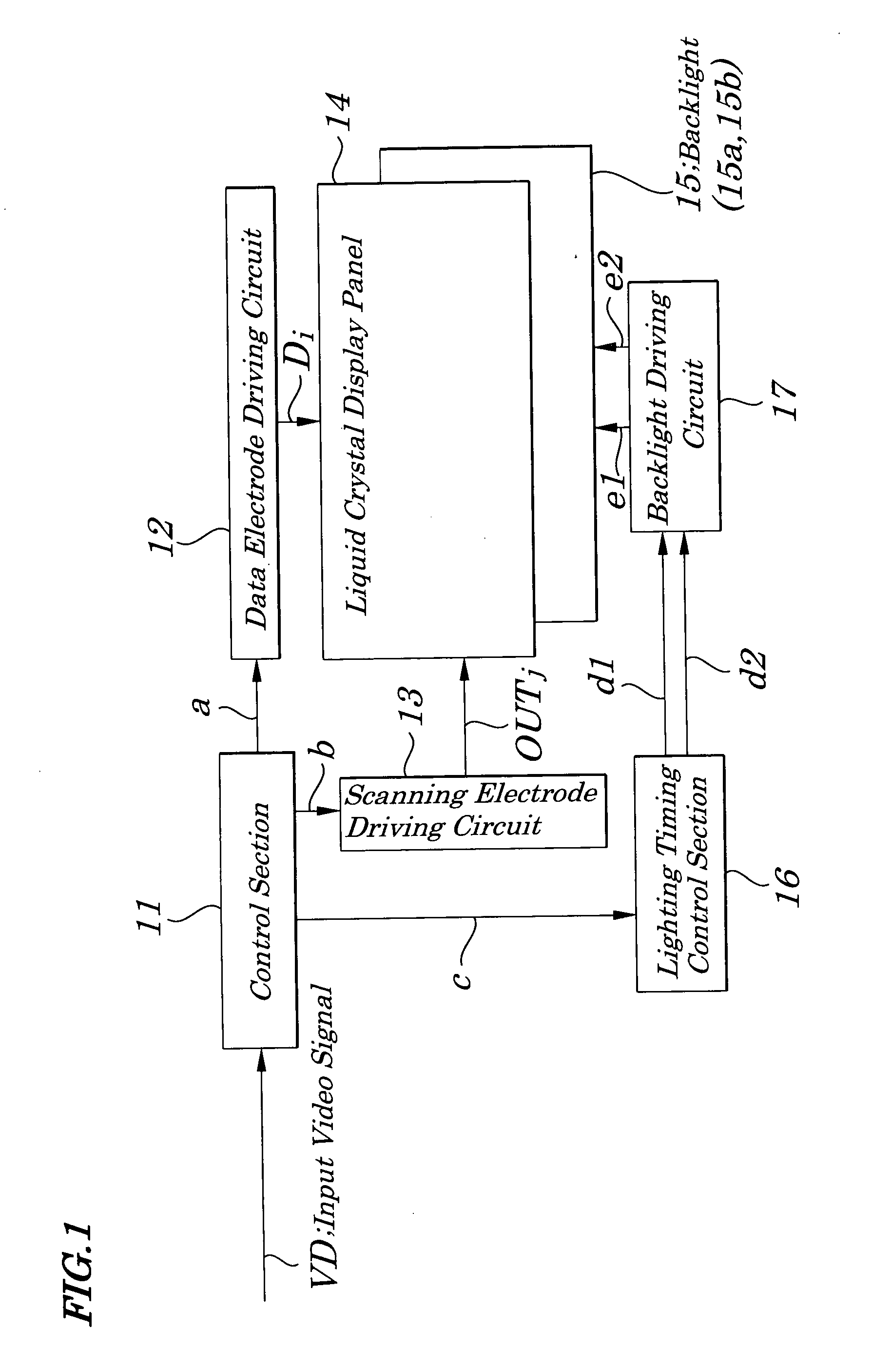
[0045]FIG. 1 is a block diagram showing electrical configurations of main components of a liquid crystal display device of a first embodiment of the present invention. The liquid crystal display device of the first embodiment includes, as shown in FIG. 1, a control section 11, a data electrode driving circuit 12, a scanning electrode driving circuit 13, a liquid crystal display panel 14, a backlight 15, a lighting timing control section 16, and a backlight driving circuit 17.

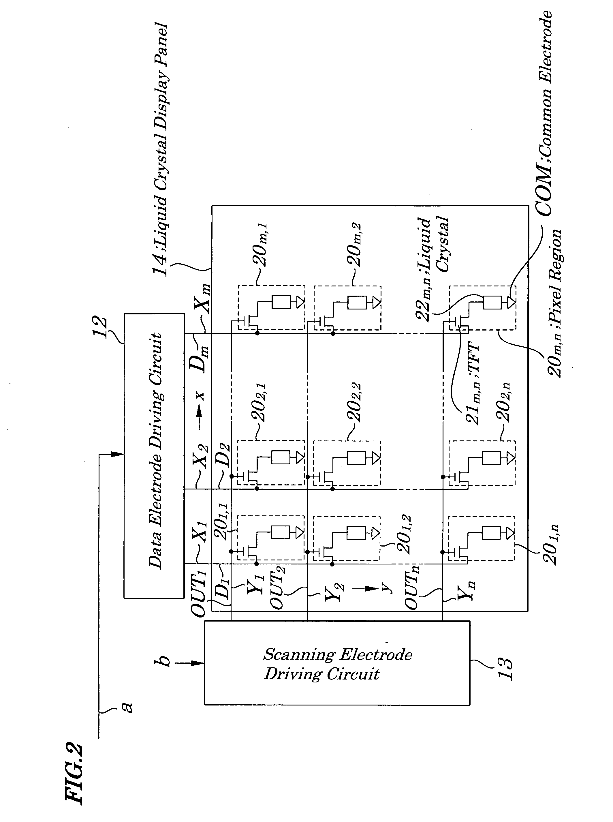
[0046]FIG. 2 is a schematic circuit diagram showing an example of electrical configurations of the liquid crystal display panel 14 shown in FIG. 1. The liquid crystal display panel 14 is of a transmission-type which allows light of the backlight 15 to enter and, as shown in FIG. 2, includes data electrodes Xi (i=1, 2, . . . , m, for example, m=640×3), scanning electrodes Yj (j=1, 2, . . . , n, for example, n=512), and pixel regions 20i,j. The data electrodes Xi are mounted at specified intervals in an x directi...

second embodiment

[0058]FIG. 6 is a block diagram showing electrical configurations of main components of a liquid crystal display device according to a second embodiment of the present invention. In FIG. 6, the same reference numbers are assigned to common components having the same functions as in the first embodiment shown in FIG. 1. In the liquid crystal display device of the second embodiment, as shown in FIG. 6, instead of a control section 11, a control section 11A having functions being different from those of the control section 11 is incorporated newly. The control section 11A, when making each of LED blocks 15a and 15b flash two times during one frame, applies a voltage to each of pixel regions 20i,j in a manner in which the polarity of the voltage changes in every period during which the LED blocks 15a and 15b are being lit. Configurations other than described here are the same as in FIG. 1.

[0059]FIG. 7 is a time chart explaining operations of the liquid crystal display device of FIG. 6....

third embodiment

[0061]FIG. 8 is a block diagram showing electrical configurations of main components of a liquid crystal display device according to a third embodiment of the present invention. The liquid crystal display device of the third embodiment, as shown in FIG. 8, includes, instead of the control section 11, the backlight 15, the lighting timing control section 16, and the backlight driving circuit 17 shown in FIG. 1, a control section 11B, a backlight 15A, a lighting timing control section 16A, and a backlight driving circuit 17A, each of which has a function being different from that provided by each of the components shown in FIG. 1. The backlight 15A is made up of LEDs as in the case of the backlight 15, but made up of one light emitting region and is not divided into two portions.

[0062] The control section 11B, as in the case of the control section 11, sends out a controlling signal “a” to a data electrode driving circuit 12, a controlling signal “b” to the scanning electrode driving ...


PUM


Abstract

A liquid crystal display device is provided which improves quality of images made up of moving images and images having moving images and still images in a mixed manner. Each frame of an input video signal having a specified frame frequency (60 Hz) is divided into four sub-frames each having a frequency being four times as large as the specified frame frequency and, after an overdriving operation is performed in the first sub-frame on each pixel region of a liquid crystal display panel, a normal driving operation is performed in the second sub-frame and thereafter, and in which a backlight flashes two times at a frequency being two times as large as a frame frequency (120 Hz) of the first frame frequency during one frame period in specified time intervals.

Description

BACKGROUND OF THE INVENTION [0001] 1. Field of the Invention [0002] The present invention relates to a liquid crystal display device, a driving control circuit to be used in the liquid crystal display device, and a method for driving the liquid crystal display device and more particularly to the liquid crystal display device having an LED (Light Emitting Diode) backlight being able to be suitably used when only moving images and moving / still images having moving images and still images in a mixed manner are displayed, to the driving control circuit, and to the method for driving the liquid crystal display device. [0003] The present application claims priority of Japanese Patent Application No. 2006-055600 filed on Mar. 1, 2006, which is hereby incorporated by reference. [0004] 2. Description of the Related Art [0005] In recent years, a liquid crystal display device has been used not only as a monitor of a personal computer but also as various displays such as a liquid crystal televi...

Claims


Application Information

Patent Timeline
IPC IPC(8): G09G3/36
CPCG09G3/3406G09G3/3648G09G2340/16G09G2340/0435G09G2310/0245
Inventor HONBO, NOBUAKIHADA, HIROSHI
Owner NEC LCD TECH CORP
Why Eureka
Try Eureka