Back light unit

a back light and unit technology, applied in the field of keypad devices, can solve the problems of product quality deterioration, increase in power consumption, and increase in manufacturing costs, and achieve the effects of reducing cost, reducing manufacturing costs, and reducing manufacturing costs

Inactive Publication Date: 2008-01-24
HB TECH CO LTD
View PDF4 Cites 33 Cited by
  • Summary
  • Abstract
  • Description
  • Claims
  • Application Information

AI Technical Summary

Benefits of technology

[0014]An aspect of exemplary embodiments of the present invention is to address at least the problems and / or disadvantages and to provide at least the advantages described below. Accordingly, an aspect of exemplary embodiments of the present invention is to provide a back light unit for a keypad of an input device, in which a light guide plate having a light guide pattern part based on a predetermined regularity can be of thin transparent resin having a predetermined hardness, for solving an assembly problem and a light loss problem caused by adhesion despite having flexibility and a transmittance property, thereby acquiring a minimum luminance required for a light source, and achieving a cost reduction, a slim design, and a minimization of power consumption.

Problems solved by technology

The back light unit of the type in which the plurality of LEDs are directly disposed at the back of the key has a drawback that a manufacture cost increases because the LEDs are required as many as the number of the keys, and an amount of power consumption increases.
However, this method has a serious disadvantage in which a product quality is deteriorated because a constant luminance is not provided as much as required every key, and a distribution of luminance between the keys is great.
Also, this method requires still many LEDs smaller than the number of the keys.
The back light unit of the type in which a surface light emitting plate device such as the OLED in place of an LED is disposed on an upper surface of a contact switch and keys are again disposed on the upper surface thereof has drawbacks of deteriorating light efficiency of the device itself, increasing a manufacture cost of the OLED because of a great prime cost, additionally requiring a separate power supply using alternate current driving, causing a noise due to the alternate current driving, and increasing a cost for additional solutions thereto.
However, the edge light type back light unit cannot be used as a key backlighting back light unit for an input device such as a telephone and a mobile phone because its light guide plate is of acrylic resin not almost bent.
However, this method causes another problem of deteriorating a product elasticity for bending and restoring the silicon light guide plate to an original state because of excessive flexibility, in case where the silicon light guide plate is manufactured as a thin film having a thickness of 1 mm or less.
In particular, the silicon light guide plate is bent as mounted when there exists a bending part of the keypad such as a metal dome switch, thereby destroying a horizontal alignment of a light source and the light guide plate, and causing a loss of light incident on an end of the light guide plate.
Also, there occurs a drawback that the bending of the light guide plate causes an increase of an amount of light incident at an angle of less than a critical angle for total reflection and not totally reflecting within the light guide plate, and thus causing light loss outside the light guide plate in course of light guide.
Therefore, the silicon light guide plate is adhered to other parts upon keypad assembly, thereby making it difficult to minutely adjust and assemble the light guide plate in a regular position.
Thus, the conventional back light unit has a drawback that a product is greatly deteriorated in its appearance because light leaks out from an edge of the product.
However, a key backlighting back light unit has a great difficulty and thus has no possibility in attaching a reflection sheet to an external part of a light guide plate because the light guide plate has a very small thickness of less than 0.1 mm to 1 mm because of a product characteristic.
The key backlighting back light unit is difficult to expect even the improvement of light efficiency because it cannot achieve an effect of perfect adherence to an edge.
In other words, this drawback results in a loss of a large amount of light and therefore, causes a disadvantage that the number of light sources should increase by an amount of lost light to acquire a required amount of light.

Method used


Image

  • Back light unit
  • Back light unit
  • Back light unit

Examples


Embodiment Construction

[0074]Exemplary embodiments of the present invention will now be described in detail with reference to the annexed drawings. In the following description, a detailed description of known functions and configurations incorporated herein has been omitted for conciseness.

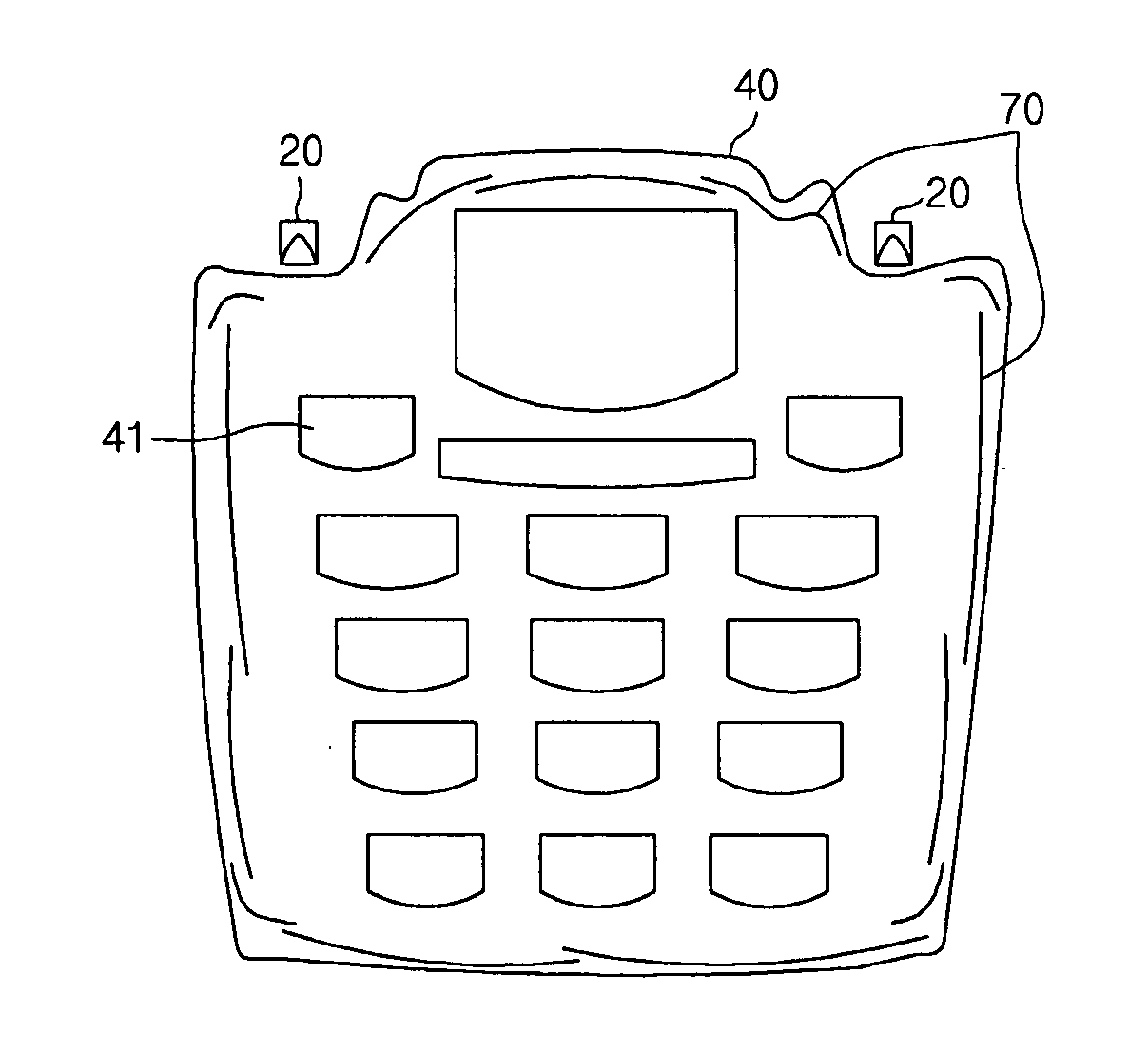
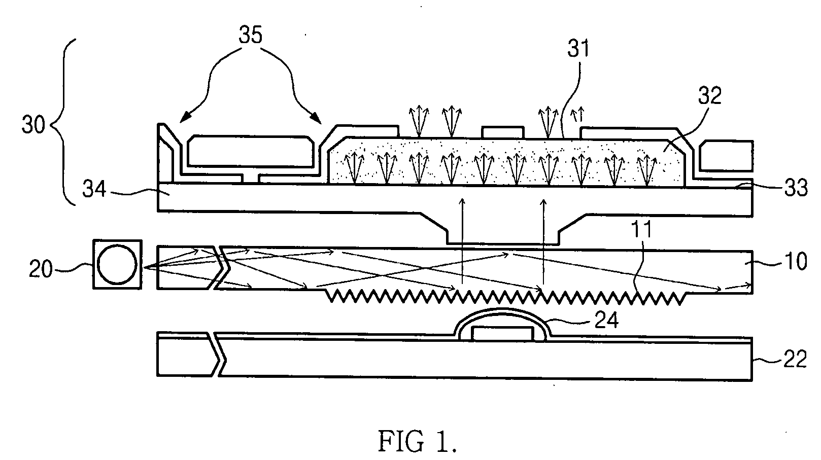
[0075]FIG. 1 is a cross-sectional diagram illustrating a key backlighting back light unit according to the present invention. An input device for a telephone or a mobile phone includes a light guide plate 10 having a light guide pattern part 11 on its lower surface, and diffusing and scattering light with a uniform illuminance at a required light emitting region; at least one light emitting unit 20 provided at a sidewall of the light guide plate 10, and irradiating light to the light guide plate 10; a keypad 30 positioned over an upper surface of the light guide plate, and including a resin layer 32, a base resin layer 34, and a character opening part 31 having a character shape, a key assembly 35 provided at one side,...


PUM


Abstract

Provided is a back light unit. The back light unit includes a light guide plate having a light guide pattern part; at least one light emitting unit provided at a sidewall of the light guide plate, and irradiating light to the light guide plate; a keypad positioned over the light guide plate, and comprising a resin layer, a base resin layer, a character opening part having a character shape, a key assembly provided at one side, and a key adherence film provided on an upper surface of the base resin layer; and a printed circuit board comprising a metal dome switch positioned under a lower surface of the light guide plate.

Description

BACKGROUND OF THE INVENTION[0001]1. Field of the Invention[0002]The present invention relates to a keypad apparatus for an input device having a backlighting function, such as a mobile phone, a telephone, a Portable Digital Assistant (PDA), a keyboard, or a calculator, and more particularly, to a back light unit for a keypad apparatus, having an easy bending property, flexibility, and optimal transmittance and preventing light leakage at an edge.[0003]2. Description of the Related Art[0004]A light receiving type flat panel display such as a liquid crystal display (LCD), a keypad back light unit for a telephone or a mobile phone, or a back light unit for a lighting signboard has been disclosed in Korean Patent Application Nos. 10-1997-0073783, 10-1998-0030060, 10-1999-0047621, 10-2000-0063111, 10-2001-0073468, 10-2005-0062790, and 10-2005-0062797, and Korean Utility Model Application No. 20-1996-0047524. The above key backlighting back light unit for an input device disclosed in the ...

Claims


Application Information

Patent Timeline
Patent Type & Authority Applications(United States)
IPC IPC(8): G01D11/28
CPCG01D11/28G02B6/002G02B6/0036G02B6/0038G02B6/0043G02B6/0051H01H2219/062G02B6/006G06F3/0202H01H2219/044H01H2219/046H01H2219/056G02B6/0055Y10S362/80
Inventor PARK, DEUK IIRHEW, CHOONG YOPBALK, KI YONGHYUN, YOUNG JINLEE, JUN KYUCHO, HYUN JUNGCHOI, KYU JIN
Owner HB TECH CO LTD
Why Eureka
Try Eureka